Which one are you talking about? I tried it with cap values of 0.01uF to 20uF for the first cap and the results were the same.
You seem to be using current sources in your PSUD model. That's not a very realistic representation of how tubes conduct at start up. At the very least I would replace the current sources with resistors instead, so the load current is proportional to the supply voltage, rather than always at maximum.
Which one are you talking about? I tried it with cap values of 0.01uF to 20uF for the first cap and the results were the same.
C1 and C2 (and probably C3). Referring to the PSUD schematic.
20uF should be enough for all three. C3 can still be on the large side, but expect to see similar current draw if you do (because, if the input side comes up instantaneously, there's about 500VDC across 330 ohms, or 1.5A peak again). So you might increase the resistor, which will drop DC, so you may have to change a few things elsewhere in the circuit.
A larger choke would be very helpful, too. Your load resistance equivalent is about 2.5kohms. Your filter values are around 100 ohms. Mismatched filters are undesirable. Not that you'd expect to be able to achieve a 2500 ohm, << 120Hz filter (for C = 20uF, you'd need L = 125H), but a higher impedance (meaning, smaller C and larger L, while keeping the L*C product constant so your ripple attenuation stays constant) is definitely desirable.
I should think a 5 or 10H choke would be easily enough available, without spending much DCR, or wasting space or $ (hah, size, weight and cost are usually seen as positive attributes anyway, so go nuts).
BTW, the power transformer's DCR should include the primary side resistance. If it's a dedicated (one secondary) transformer, then the secondary referred equivalent will be about double the secondary DCR (which is to say: the primary and secondary winding losses will be balanced). Or you can measure it directly (i.e., primary side referred), and convert it to secondary-referred by using the square of the turns (aka voltage) ratio. If it's not a single-output transformer, then, simply ignoring the other windings and proceeding as above, will give you a slightly optimistic output voltage, but it'll still be close enough.
Tim
You seem to be using current sources in your PSUD model. That's not a very realistic representation of how tubes conduct at start up. At the very least I would replace the current sources with resistors instead, so the load current is proportional to the supply voltage, rather than always at maximum.
I can't seem to be able to do that. I can only replace the last current source with a resistor, but the intermediate ones can't be replaced with resistors. Or I can't seem to figure out how.
@ Sch3mat1c
That's a lot of info, I need to soak it in 🙂 Thanks for the detailed explanation.
I only used PSUD a couple of times, years ago, but IIRC I think you have to demolish the whole filter chain and rebuild it with resistor-loaded stages instead. Or just use a proper circuit simulator.I can't seem to be able to do that. I can only replace the last current source with a resistor,
I have the whole circuit in LTSpice, and I have an even larger current spike there.
So that should be as real as I can simulate it (I think).
But I will play with the cap/choke values and see if I get a better result.
So that should be as real as I can simulate it (I think).
But I will play with the cap/choke values and see if I get a better result.
C1 and C2 (and probably C3). Referring to the PSUD schematic.
20uF should be enough for all three. C3 can still be on the large side, but expect to see similar current draw if you do (because, if the input side comes up instantaneously, there's about 500VDC across 330 ohms, or 1.5A peak again). So you might increase the resistor, which will drop DC, so you may have to change a few things elsewhere in the circuit.
A larger choke would be very helpful, too. Your load resistance equivalent is about 2.5kohms. Your filter values are around 100 ohms. Mismatched filters are undesirable. Not that you'd expect to be able to achieve a 2500 ohm, << 120Hz filter (for C = 20uF, you'd need L = 125H), but a higher impedance (meaning, smaller C and larger L, while keeping the L*C product constant so your ripple attenuation stays constant) is definitely desirable.
I should think a 5 or 10H choke would be easily enough available, without spending much DCR, or wasting space or $ (hah, size, weight and cost are usually seen as positive attributes anyway, so go nuts).
Tim
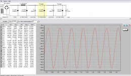
I tried a sim where I used 20uF for all three caps and also used a 10H choke.
The result is a ripple of 750mV vs a 110mV as I had in the first version (after the choke). With a 5H choke the ripple was double.
This way the current spike is around 1A.
What I want to understand is this:
Does the smaller 1A current ripple justify the use of a larger and more expensive choke, and this way having a x7 ripple versus trying to address the current spike in my first version with an auxiliary circuit? Something with a relay that shorts some resistor or thermistor after a few seconds?
Also I added 3 ohms for the primary DCR. I figured it couldn't be more than that. There will be a HV transformer and another smaller one for the heaters/bias etc
Attachments
Last edited:
I think the advice you've gotten to increase the choke value is right on. You may as well not have a choke with the previous choke you had. And again, that 20uf first cap is good advice whether you believe it or not. That combination will go far to tame that choke surge. I'm not so sure it's a good idea to have such small 20uf caps after the choke. That's what's causing the higher ripple in your sim, not the choke replacement. The 20uf first cap and the much higher 5 to 10 henry choke value is just good practice for the current you're running.
With 20uF/10H on the input I get about 150mV ripple. Still a tad higher than with 235uF/1.2H.
What I'm trying to understand is this. How is it better? I thought the main criteria for a rectifying filter is to smooth out AC, to have as little ripple as possible.
Given the two scenarios, the higher capacitance/lower inductance wins from a price and performance point of view.
Is there anything else that should be considered that would justify the x10 value choke? (and possibly way higher price of it). As it stands, I already ordered the transformer, and that means that I can't afford any increase in the DCR of the choke, and to be able to get it at 50-60 ohms I would need to use thicker wire, and that would make the choke pretty huge, and again, expensive.
You can if you simply add a resistor! 😛As it stands, I already ordered the transformer, and that means that I can't afford any increase in the DCR of the choke,
Check out the 159Q here:
Hammond Mfg. - D.C. Filter Chokes - (153 - 159 Series)
You have to be careful about the voltage rating, though. It's right on the edge but should work. I don't know if you have access to Hammond where you're located but that line of choke shouldn't be out of line pricewise. They are not pretty though so you would want to hide it.
True, I'll look and see what can be done on the choke side of things.
Still, I'd like to also look into the NTC direction, but I wasn't able to find good information on how to calculate the value needed for my application.
Still, I'd like to also look into the NTC direction, but I wasn't able to find good information on how to calculate the value needed for my application.
Check out the 159Q here:
Hammond Mfg. - D.C. Filter Chokes - (153 - 159 Series)
You have to be careful about the voltage rating, though. It's right on the edge but should work. I don't know if you have access to Hammond where you're located but that line of choke shouldn't be out of line pricewise. They are not pretty though so you would want to hide it.
It has a 150mA rating, my amp is at 250mA idle and 350ma full power. I don't think it's wise. Also the inductance falls with current so I don't think it's a good idea.
You may be right. I was looking at the main B+ current of 150 to 160 ma. At any rate if you don't understand why the small cap in front is necessary for a high quality power supply then reread my replies in #8 and #11. If you still don't understand then it's time to hit the books and don't just ask questions whose answers you do not believe. Morgan Jones' books are a good place to start.
Trileru,
I would suggest that any current surge through the choke at turn on is not a practical problem in itself. The choke will survive.
With respect to simulation during turn-on, as Merlin says the load characteristic is not well represented by a constant current. If the loads are valves, then unless you have a hot-start condition, the valve warm up times will dictate the response. Also, the simulation (PSUD2 or LTSpice) is not representing choke inductance variation with applied AC voltage or DC current, so caution is needed when interpreting the sim response.
You can check the response of the power supply LC interaction by applying a step load via the various current sources to look for ringing.
I have used a number of 1.2-1.8H chokes for extra smoothing in CLC filters - that choke size is a common recycled flourescent light choke value for 240VAC mains that happily copes with at least 400mADC (http://dalmura.com.au/projects/Choke%20measurement.pdf)
I made some sims and indeed the conduction angle is a bit longer with 23.5uF cap on the input, and the current peaks are a tad lower. And on the first cycles indeed the current spikes are way smaller.
I must deal with two more things if I do this.
First, the overall voltage is lower, especially under full load. I lose about 20V I think.
Second, I noticed this and maybe need some clarification.
The current peaks on the first cap are about 1.14a to 1.45A depending on the load.
The 470uF caps (in series) that I planned on using on the first iteration have a rated ripple current of 2.51A at 85°C/120Hz.
Most of the ones I can find at 47uF (400-500V) have a rated ripple current of about 420mA at 120Hz. I will need it for 100Hz but almost the same. The best one seems to be this: 47uF/400V - http://www.farnell.com/datasheets/24536.pdf with a rated ripple of 1.2A at 100Hz/40°C or 0.79A at 100Hz/85°C.
Even so, I'd need to buy 4 and put them two by two in parallel/series to share the current.
Is that correct?
After reading Valve Amplifiers I decided to make some more sims.
I also used resistors instead of current sinks.
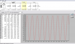
Using a 23.5uF (practical value) for the first cap I got peaks of 1.06A on the first cap (after the ps settled).
Using a 235uF (practical value) for the first cap I got peaks of 1.11A on the first cap (after the ps settled).
The effective reduction is of 50mA. As an absolute, this could be considered an advantage.
Then I looked at the current spike on the choke and indeed there's a difference. With a 235uF cap (1H/100uF) on the first position there's a max of 1.35A on the choke.
With a 23.5uF cap (10H/335uF second cap) on the first position there's a max of 1.74A on the choke.
So this is a disadvantage. Again, how much that counts in real life I don't know.
I then looked at the current surges on the first cap at startup and the winner is the setup with the 23.5uF cap in the first position.
These are the results:
23.5uF/10H/335uF:

235uF/1H/100uF:

Of course these surges will be dealt with with the use of a thermistor that will be short circuited after some time.
So that leaves me with the question:
Is it worth, from a practical side of things, to try and find high current ripple rated 47uF high voltage caps to connect them in series/parallel and then spend the extra cash on the large 5-10H (400mA/ 50-100ohms DCR) choke?
After looking at Mr. Jones's examples I stumbled upon his HV power supply used in the "Daughter of the Beast" amplifier. This is the schematic he used:

As you can see, he used a 470uF/1H/470uF arrangement. Sure, the current needs are larger, 1A vs 0.35A. He also notes that the increase in size of the choke from 1H to 10H doesn't justify it.
And here's the current on the first cap in this particular PS:

Also the current into the choke:

The way he dealt with the current spike problems was simple, a thermistor on the primary. Exactly my intentions.
After reading you responses again, I went to understand and yes, I got it. The whole idea is to have lower current peaks on the first capacitor but the net gain is marginal vs the cost involved.
So again, I fail to see the benefits of doing this from a practical side of things. I guess it's more important for a tube rectifier setup, but for silicon diodes I don't see it.
@ trobbins
I took a photo of my choke's connection between the copper wire and connecting pad. As you can see there's 1-2cm of bare wire hanging in the air. Having a spike of 1.3A - 1.5A is sure to not affect it? I see that wire as a fuse, ready to blow. It's just a concern. I just want to show that in my particular situation this might be a deal breaker. I would presume that normally the connection between the copper wire and the hook-up wire is made somewhere internally where things are touching, and heat might have a flow path. In my situation I have that bare hanging wire that I presume will act exactly like a glass fuse.

Pretty hard to measure the thickness but calipers said around 0.3mm.
Anyway, I will use a NTC and avoid altogether the spike problems.
I also used resistors instead of current sinks.
Using a 23.5uF (practical value) for the first cap I got peaks of 1.06A on the first cap (after the ps settled).
Using a 235uF (practical value) for the first cap I got peaks of 1.11A on the first cap (after the ps settled).
The effective reduction is of 50mA. As an absolute, this could be considered an advantage.
Then I looked at the current spike on the choke and indeed there's a difference. With a 235uF cap (1H/100uF) on the first position there's a max of 1.35A on the choke.
With a 23.5uF cap (10H/335uF second cap) on the first position there's a max of 1.74A on the choke.
So this is a disadvantage. Again, how much that counts in real life I don't know.
I then looked at the current surges on the first cap at startup and the winner is the setup with the 23.5uF cap in the first position.
These are the results:
23.5uF/10H/335uF:
235uF/1H/100uF:
Of course these surges will be dealt with with the use of a thermistor that will be short circuited after some time.
So that leaves me with the question:
Is it worth, from a practical side of things, to try and find high current ripple rated 47uF high voltage caps to connect them in series/parallel and then spend the extra cash on the large 5-10H (400mA/ 50-100ohms DCR) choke?
After looking at Mr. Jones's examples I stumbled upon his HV power supply used in the "Daughter of the Beast" amplifier. This is the schematic he used:
As you can see, he used a 470uF/1H/470uF arrangement. Sure, the current needs are larger, 1A vs 0.35A. He also notes that the increase in size of the choke from 1H to 10H doesn't justify it.
And here's the current on the first cap in this particular PS:
Also the current into the choke:
The way he dealt with the current spike problems was simple, a thermistor on the primary. Exactly my intentions.
After reading you responses again, I went to understand and yes, I got it. The whole idea is to have lower current peaks on the first capacitor but the net gain is marginal vs the cost involved.
So again, I fail to see the benefits of doing this from a practical side of things. I guess it's more important for a tube rectifier setup, but for silicon diodes I don't see it.
@ trobbins
I took a photo of my choke's connection between the copper wire and connecting pad. As you can see there's 1-2cm of bare wire hanging in the air. Having a spike of 1.3A - 1.5A is sure to not affect it? I see that wire as a fuse, ready to blow. It's just a concern. I just want to show that in my particular situation this might be a deal breaker. I would presume that normally the connection between the copper wire and the hook-up wire is made somewhere internally where things are touching, and heat might have a flow path. In my situation I have that bare hanging wire that I presume will act exactly like a glass fuse.
Pretty hard to measure the thickness but calipers said around 0.3mm.
Anyway, I will use a NTC and avoid altogether the spike problems.
Last edited:
With 20uF/10H on the input I get about 150mV ripple. Still a tad higher than with 235uF/1.2H.
What I'm trying to understand is this. How is it better? I thought the main criteria for a rectifying filter is to smooth out AC, to have as little ripple as possible.
Well, I don't know... you didn't specify how much ripple is required, and apparently you haven't been consistent about what current draw is required, because I now see that the maximum requirement is up to 350mA! 😱 😱 And you've been showing considerable worry over this inrush issue, while at the same time, you haven't asked the important question: how much inrush is actually tolerable?
I took a photo of my choke's connection between the copper wire and connecting pad. As you can see there's 1-2cm of bare wire hanging in the air. Having a spike of 1.3A - 1.5A is sure to not affect it? I see that wire as a fuse, ready to blow. It's just a concern.
FWIW, the fusing current of copper is a great many times the steady-state rating, and that still requires a sustained second of fault current before it finally opens up.
Indeed, the location shown is not the most likely failure spot. It's open to air, and is connected to a large metal lug, which provides additional heatsinking. The most likely spot is deep within the winding, where wire is surrounded by wire, all of it very rapidly heating up if a short circuit occurs. So any given piece of wire, down in the center, only has to heat itself up, and doesn't have to overcome any heat conduction to its neighbors, because they are all heating up as well.
But an ampere peak, and tens of milliseconds? Your worries are misplaced. You can go more like tens of amperes and whole seconds before that thing smokes! 🙂
The limiting elements are probably the capacitors (which are rated for some amount of surge voltage and current) and rectifier diodes (which are rated for exactly this kind of surge, usually around 20A for diodes this size). You should worry more about your power switch, because it will spark a little bit, each time you turn this on; but that's just a matter of getting a big enough (5 or 10A?) switch, no worries.
Tim
- Status
- Not open for further replies.
- Home
- Amplifiers
- Tubes / Valves
- HV soft start