Thankyou Gorgon. I look in occasionally but mostly move on.
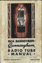
Here are the 82 & 83 specs from 1933. The 81 got in too. it was on the opposite page of the scan.
These tubes can create quite a bit of noise both internally in your circuit as well as radiate. EMI & EMC
I'd recommend something like 1/2W CC resister of 50 to 100 R in each plate. Not a cure all but will help.👍
Attachments


Sorry for the above. I meant to say I've installed a CL-90 in the HV lead per my advisor's directions. Worked fine both before and after installation.
I have only experience with large MV rectifiers feeding Rf-generator tubes (over 10-12kV, 6-12A dc).
They where ok with a 5min delay when switched (used) on a daily basis, but after the summer, during which the factory was shut down for a couple weeks, at least 15min delay where needed to be sure they will not backfire. Spare tubes, just to make sure, where heated 30min before HV was applied.
I am curious to learn more of your own or anyone else’s experiences with a backfire event. I gather there is an arc flash (potential for rf burns to skin and eyes) and arc blast from debris. Is there much of a bang from the spark. I figure correct design with fast blow fuses should prevent the worst of that.
Do the tubes sometimes survive the event.
In theory I assume the arc is non rectified ac for however many cycles. What is the return path, via the LC, or does the arc go through both diodes simultaneously. Perhaps the filament transformer forms a return path; would that step it up to an EHT transient on the primary.
Thank you for any insight to these questions in theory or in practice.
Last edited:
Arc-back and/or flashing is the same type of event as with a typical vacuum rectifier - reverse current flows during the time when it should be blocked by the PIV capability. For audio/commercial situations, this typically stresses the power transformer HT secondary from higher current than normal for the duration of the reverse voltage condition. Over-current protection would need to be in the secondary side phase arms, or in the primary winding - however that takes detailed design effort to choose the fuse, and to assess whether the fuse could save the power transformer windings. The simplest path to take is to add series ss diode protection to each rectifier anode, as that avoids the fault from occurring for starters.
CL90 is a very addition to most circuits.Sorry for the above. I meant to say I've installed a CL-90 in the HV lead per my advisor's directions. Worked fine both before and after installation.
Most industrial installations are 3-phase, in which case the heaters are powered by the quadrature method.I have only experience with large MV rectifiers feeding Rf-generator tubes (over 10-12kV, 6-12A dc).
That subject is well outside most of DIY. But I will post something later to cover that.
When I was much younger & still had hair & teeth I spent a couple of years at Ferranti in Canada in the transformer section.
The transformers were mostly 3-phase, the size that ships on a railway flat car.
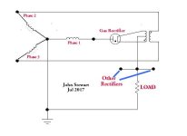
The schematic shows the Quadrature heater connexion for gas & Hg rectifiers in 3-phase AC to DC conversion.
Each of the phases is 120 degrees apart from the others,. The voltage across the ends is root of 3 (1.73205) times the leg voltage.
With this hookup to the heater transformer the power is applied in quadrature to the HV to be rectified.
A commons 3-phase setup would use six diodes, The max current is delivered at the middle of the heating cycle.
The result is each of the diodes is able to deliver a larger current then possible in a single phase circuit. 👍
Attachments
When I was at a Navy school for a low frequency transmitter, the other electronic technicians on my ship installed our new low frequency transmitter.
When I got back to the ship to check out the new transmitter, I quickly discovered something was wrong.
It did not take me long to discover they only connected 2 of the 3 phases. You would not believe the reflected high voltage on the unconnected phase.
I brought in the 3rd phase wire.
Problem solved!
Industrial gear has crude, but multiple protection, additionally, the tubes are inside a completely closed cabinet with water/air heat exchanger. Cabinet doors have a small window that allows to safely visual check the condition of the tubes before opening the doors. Under this conditions any danger to any of the factory workers is very unlikely.I am curious to learn more of your own or anyone else’s experiences with a backfire event. I gather there is an arc flash (potential for rf burns to skin and eyes) and arc blast from debris. Is there much of a bang from the spark. I figure correct design with fast blow fuses should prevent the worst of that.
Do the tubes sometimes survive the event.
In theory I assume the arc is non rectified ac for however many cycles. What is the return path, via the LC, or does the arc go through both diodes simultaneously. Perhaps the filament transformer forms a return path; would that step it up to an EHT transient on the primary.
Thank you for any insight to these questions in theory or in practice.
Offcourse backfiring (practically a shorted secundary, leading to severe core saturation and primary current) an extreme stress situation until the power gets shut off, not only for the tubes, but also the rest of the circuit that has to deal with a shorted secundary.
Usually it was enough to just look through the window for any visible damage of the tubes before opening the doors, make sure nothing else got damaged, wait 15min or so, and restart again.
Tubes never exploded, but sometimes the short forced a ceramic winding support out of place and it was crucial to fix that before any restart attempt.
If left unattended, it was only a question of days before the need of a new transformer , and without a spare transformer at hand it ment forced holidays for a lot of people.
Happend only once in my time, but it cured the factory workers(pressured by theyr bosses to reduce production start up time) desire to fiddle with the delay timer settings.
Last edited:
Good for you!. Your buddies probably left it off to see how long you took to locate the fault! 😀I brought in the 3rd phase wire.
Here, big 3-phase circuit brakers or switching devices (do not know how they are called in english) usually interrupt under grossly unbalanced load conditions.
One effective form of load correction in 3-phase circuits is the Zig-Zag transformer.Here, big 3-phase circuit brakers or switching devices (do not know how they are called in english) usually interrupt under grossly unbalanced load conditions.
Something I've never seen any data nor much anecdotal experience is regarding normal service life expectancy i.e. so many (?) thousand hours before cathode emission drops off. Perhaps they have a reputation of needing more/less/similar frequent replacement than vacuum types. I am guessing as I’ve not read anything bad in this regard, then they either last much the same as any other tube or go on forever. Would a worn filament be indicated by excessive voltage drop at high current.
I read the following in a book which I hope I am okay to quote without breaking any copyright: Valve Amplifiers by Morgan Jones ( a good read)By this argument, a semi-con rectifier is superior, so why bother with a toxic, twitchy, drama queen antique? Can anyone name a single virtue of gas discharge rectifiers that isn't better with cheap drama-free semi-cons?
All good fortune,
Chris
"to give electrical performance very slightly better than silicon. (No charge storage to cause current overshoot)"
You could do a comprehensive search via Google & probably the data you are looking for will appear.Something I've never seen any data nor much anecdotal experience is regarding normal service life expectancy i.e. so many (?) thousand hours before cathode emission drops off. Perhaps they have a reputation of needing more/less/similar frequent replacement than vacuum types. I am guessing as I’ve not read anything bad in this regard, then they either last much the same as any other tube or go on forever. Would a worn filament be indicated by excessive voltage drop at high current.
Or wait for someone else to do & then hope it would get posted on DIY,
Might be a while! 😀
You need to research the first Trans Atlantic phone cable.
Western electric built tubes for that. The were made to last "forever".
If one tube in a lot was not good, they crushed the whole lot. Then another lot was built.
Tube failure was not a good thing; nobody could go diving to repair that system.
The first cable across the English Channel was for telegraph.
It did not work!
Well, the person at the Key was sending code too fast.
The capacitance of the cable was integrating the rise and fall of the voltage, when the key turned the current on and off.
When they figured that out, they had to send longer dots and longer dashes, with lots of time between the characters.
The next statement is not true, but you may find the story entertaining.
Apparently Samuel F. B. Morse and Ludvig van Beethoven were working together, and they made reference to the Roman numbering system.
Beethoven wrote a symphony where, his first few bars started with dit dit dit dah, dit dit dit dah, etc.
The Roman numeral V in morse code is dit dit dit dah, just the same as Beethoven's opening bars.
And then Symphony number V was published.
A similar connection was made in Stanley Kubrick's 2001 - A Space Odyssey.
The onboard computer's name was HAL. Each letter in Hal's name is one letter removed from IBM.
Last edited:
Microsoft used HAL too, as Hardware Abstraction Layer.
And V in morse should be dit dit dit dit dah (….-)
Regards, Gerrit
And V in morse should be dit dit dit dit dah (….-)
Regards, Gerrit
In industrial use, some 8000h/year, MV-rectifiers where replaced after 4- 5 years, often together with the transmitting tube at theyr end of life.
But it all depends on storing and operating condions, there where big differences in lifespan, sometimes a tube made it barely to 3000h, on one occasions a Philips YD1212 made it to 60oooh and had still some life left (i changed it only because efficiance had dropped to the point it made sense to replace it), but 30-40oooh was about average of use before replacement.
But it all depends on storing and operating condions, there where big differences in lifespan, sometimes a tube made it barely to 3000h, on one occasions a Philips YD1212 made it to 60oooh and had still some life left (i changed it only because efficiance had dropped to the point it made sense to replace it), but 30-40oooh was about average of use before replacement.
Last edited:
gorgon53,
The intrinsic value of the Morse code is Efficiency.
4 dits, and a Dah takes 5 characters, and 5 spaces. Ineficient.
When properly learned, the morse code is strictly reflex recognition of the Sound, and not the number of dit's and dah's.
The Russians were transmitting and receiving at 60 words per minute. Back then, the "one time pad" was used for encryption, and the encrypted letters and numbers were transmitted that way. There were no electronic crypto machines for Russia, that was an unknown luxury back then.
In order to communicate effectively, the Russian radiomen had to copy 60 WPM (Words Per Minute).
The original Press teletypes that transmitted News on shortwave HF channels were 60 WPM.
Those machines sounded like an idling motor, compared to Teletypes' 100 WPM machines for the US Govt.
- Home
- Amplifiers
- Tubes / Valves
- HV delay for 83 tube rectifier