I have an old ARC SP8, that I now have working much better thanks to the clever folks on this forum 🙂
Last thoughts required to cure the hum that remains, I have go this a lot better with trial and error, but I can't seem to loose the last bit.
The below has worked, but still residue remains - any tricks or ideas welcomed
I have Shielded the DC heater cables
I have put in some additional steel plates as shields around the mains transformer to block the path towards the line stage valves.
I am going to replace the smoothing caps in the HT and LV supplies, but would love to hear any other experiences.
Thanks
What's the measured noise floor you're seeing? I should have the one I have here repaired shortly as a comparison.
I can't measure anything so just ears. Full volume can easily hear across the room - no volume off mute a low level that can be heard at listening position but not loud
If hmm is in both channels, You can change electrolit. capacitors in power supply /they are very old.
yeah slightly more in left channel then right, but yeah both channels.
I will swap out the old electrolytic caps in the next couple of days, fingers crossed.
For the Power supply on LV side I wonder if there is a maximum capacity I can put in. The Rev 1 of the amp I have had 2x1500 uf and the rev 5 (E) I have has 2x1000 uf and the circuit looks the same. I have 1000 uf, but could put in 3 of these, or maybe even 4?
Here is the circuit. ARCDB (Rev. 5)
....could put in 3 of these, or maybe even 4?...
It didn't hum "across the room" when new. It's not new any more; parts age. Make it as-new again, don't supersize.
Fair enough!!
"It didn't hum "across the room" when new"
That was in 1983, and my friends 1986 ARC SP10 is quiet.....so yeah.
"It didn't hum "across the room" when new"
That was in 1983, and my friends 1986 ARC SP10 is quiet.....so yeah.
Yep - always tempting to try and upgrade things while you're in there fixing them, but there's no sense going crazy.
That said, I will often go up a size or 2 (eg. From 6800 to 8200 or 10000) with main capacitors just because you can usually do it in the same footprint, the cost difference is negligible, and a little extra reserve "can't hurt".
But I wouldn't want to, say, double, or triple the specified capacitor unless it really was grossly undersized to begin with. And then you're going to want to start looking at the rectifiers, etc, and for all that, it's not likely to improve results enough to be worthwhile - if that was "underspecified", you need to wonder what else is...
Consider the power transformer's secondary winding, and consider the rectifiers.
The amp design worked well, right after it came from the factory.
Now, you are going to go install 2x, 3x, or 4x the filter capacitance.
What is the new peak current that is required during power up?
What is the new peak current when the amp is warmed up?
It does not matter if this is a preamp or a power amp.
The power transformer secondary and rectifiers are not going to be as reliable when you install the "improved" power supply parts.
Do such modifications at the risk of the amplifier circuits.
Measurements are important. There's a noise spec in the manual, either you're there or you're not.
If you have 110dB sensitive speakers and a 3000WPC amplifier, the preamp could be performing perfectly and you'd still be complaining about noise.
If you have 110dB sensitive speakers and a 3000WPC amplifier, the preamp could be performing perfectly and you'd still be complaining about noise.
What equipment do I need to measure - I am an engineer from past life so can make sense of it I am sure 🙂
I will then be able to measure it - thanks
I will then be able to measure it - thanks
PPR is correct here. Enable the amp to be overhauled without changing component values. In 99% those values make pretty much sense for this design.Yep - always tempting to try and upgrade things while you're in there fixing them, but there's no sense going crazy.
That said, I will often go up a size or 2 (eg. From 6800 to 8200 or 10000) with main capacitors just because you can usually do it in the same footprint, the cost difference is negligible, and a little extra reserve "can't hurt".
But I wouldn't want to, say, double, or triple the specified capacitor unless it really was grossly undersized to begin with. And then you're going to want to start looking at the rectifiers, etc, and for all that, it's not likely to improve results enough to be worthwhile - if that was "underspecified", you need to wonder what else is...
When I look and compare tube amp circuits from professional companies and amateurs, the pro circuits are mostly without any design flaws. Because engineers did build this amp. But when looking for the amateur section (seen hundreds or thousands of those tube amp schemos the last 20 years), much more often they have huge design flaws. Most often, the amateurs think "if I make this component twice as big, that couldn't be a mistake. Bigger is better and the new components are good for twice or maybe tripple the value of the one ones. Or, with new designs, they apply absurd high values because that couldn't be wrong and the components are so cheap.
Completely wrong thinking. A component should be as high as it must be, and not bigger. But as most amateurs fail to calculate correctly, they aim to go for those absurd high values. It's even wrong in terms of sound. High cap values make for a very lame sounding amp. But some are very clever and you can spot those circuits where they parallel a foil cap and another, even smaller foil cap to the enormous large value cap they think it sound good. This leads towards circuits, where every bigger value cap has two caps parallel. And it even sound very lame, just because they think bigger is better.
You could just put a scope on the output. The "11W" doesn't tell us how much gain the amp has. If it has 20+dB of gain and your speakers are 99dB sensitive, that would be something to address before endlessly chasing noise in the preamp.
Correct. My 99dB speakers even make the electrons thermal noise audible. It's crazy, but not so easy to build high gain, low signal amps with tubes. The whole concept of the amp must be right from the start, otherwise is will be noisy to a certain degree. But I often auditioned good tube amps that were noisy when standing in front of the speaker cone. I would call this not a design mistake, its pretty normal. The amp is pretty good, when there is no higher noise with the MC input activated in comparison to high level sources.
Last edited:
It's a DIY build power amp using 211 output valves it's a mix of my design and layout and a friends advice and skills. I believe it is actually 2V for full output if that describes sensitivity. (my friend is not interested in working on my ARC though....)
SP8 service manual is on ARC's site.
SP8_Manual_Schem.pdf - Audio Research
This may be THE most complicated tube preamp power supply I have ever seen. No, it does not need "brute force upgrade".... it was very carefully designed (and re-designed). The main filter caps charge t0 630V(!!); then a regulator drops that to 402V. So the main filter caps can have a hundred volts of ripple with very little buzz on the output. The regulator has a well-fed precision reference and a heap of gain.
Measure.... well, just monitoring the ripple on a 620V(!!) power rail will blow-up many 'scopes and technicians. Personally I would not want this on my bench: I have worked in 600V amplifiers for pay, but not for fun.
I wouldn't scope the raw rail, I would be looking at what's at the output.
Yes, a 600V rail for a 6DJ8 based preamp is about as silly as it gets. The one I have here right now suffered a shorted 1000pF cap which fried a whole pile of parts!
Yes, a 600V rail for a 6DJ8 based preamp is about as silly as it gets. The one I have here right now suffered a shorted 1000pF cap which fried a whole pile of parts!
Hum & noise; the bane of audio engineers and amp builders, it can be a nightmare to track down. first off what sort of hum is it? 50/60hz or 100/120hz or something else,knowing this gives you an idea of where the problem lies. Without a scope you could try using an online signal generator and playing a 50/100hz tone,then comparing that to your hum.
If it's 50hz then that points to heater wiring, signal wiring, heater cathode shorts and other things like shielding.
If it's 100hz that points to the PSU, AR power supplies are notoriously complex, use selected mosfets etc, apart from changing caps leave to the experts.
The next area to look at is grounding, looking for ground loops, for instance a signal cable shield is often only connected at one end to prevent a gnd loop. Bad layout of wiring can introduce issues, wiring should be as short as poss, 50hz high current wiring twisted and tucked into the corner of the chassis, stuff like that. Loads of good info here on Merlins site - How to design valve guitar amplifiers
Good luck, Andy.
Thanks everyone. I will fit the replacement (equivalent value from original) this weekend, and also have a listen to see if it's 50 or 100 hz hum. Couple of questions
What other components could go out of spec that would generate hum?
As I have fitted a new Mains transformer (to match original spec which delivers all the right voltages, and matches original spec for current). and had to do some work on shielding I wonder if more work here might be useful.
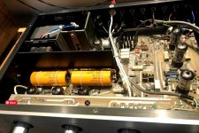
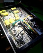
Are there any guidance on how to shield a transformer. This is what is done so far with some plates and the original chassis guard in the pictures, also shielding the DC heater cables, and the AC heater to the 6DJ8
What other components could go out of spec that would generate hum?
As I have fitted a new Mains transformer (to match original spec which delivers all the right voltages, and matches original spec for current). and had to do some work on shielding I wonder if more work here might be useful.
Are there any guidance on how to shield a transformer. This is what is done so far with some plates and the original chassis guard in the pictures, also shielding the DC heater cables, and the AC heater to the 6DJ8
Attachments
- Home
- Amplifiers
- Tubes / Valves
- Humm on old amplifier