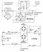
I have an Usher power amp that has a singing transformer,James Bongiorno of Ampzilla fame had an article in a recent TAS re: singing amplfiers and offered his solution in the form of a schematic for the ultimate humbuster. My knowledge of electronics is pretty basic and I was wondering if there is anyone out there that could translate this schematic into a more basic diagram? (see attached).
Thanks, David
Thanks, David
Attachments
I could totally be wrong here, but that circuit looks to me like something to "bust" ground loops. If I understand your problem, you are hearing the music coming from the amp power transformer itself. The transformer mechanically acting a little like a speaker. A ground loop would cause some low mains frequency hum in your signal chain. Totally different phenomenon from a transformer with vibrations in the laminations from the current variations.
I don;t see how a mains filter of any kind would prevent that. And if it does, I am eager to learn how.
I don;t see how a mains filter of any kind would prevent that. And if it does, I am eager to learn how.
That circuit removes some DC from the AC. It can be that un removed DC can drive the mains transformer into saturation and then a mechanical hum can be heard.
I have an Usher power amp that has a singing transformer,James Bongiorno of Ampzilla fame had an article in a recent TAS re: singing amplfiers and offered his solution in the form of a schematic for the ultimate humbuster. My knowledge of electronics is pretty basic and I was wondering if there is anyone out there that could translate this schematic into a more basic diagram? (see attached).
Thanks, David
As I understand your question the mains transformer is "singing"
due to the mains frequency and its overtones.
The diagram as shown revoves traces of DC from the mains by
insertion of the diode bridges. Especially toroidal transformers are
sensitive to this. For each half wave of ac four diodes are connected
in series. Additional caps provide some means of filtering or noise
suppression. The resistor is for discharge with open leads.
I have seen simpler arrangements with only two diodes. But JB
probably knows why he recommends this one.
Last edited:
Me again, I would like to build this, to see if it will solve the noise problem (not sure of the cost of parts?). I was wondering if there is someone out there that would like to take the time to turn the schematic into a somewhat simpler diagram with parts list for an inexperienced diyer. Please see my original post for attached "Humbuster" schematic
Thanks David
Thanks David
Last edited:
Just omit all caps and the resistor for a first tryI was wondering if there is someone out there that would like to take the time to turn the schematic into a somewhat simpler diagram with parts list for an inexperienced diyer.
I'm not certain that circuit will remove DC, unless there is no AC present. All it does is remove about 2.8V of the mains waveform. This might create switching noise, so the capacitors are added to filter this out.
To remove DC you need some back-to-back fat capacitors, with diodes to stop reverse bias.
To remove DC you need some back-to-back fat capacitors, with diodes to stop reverse bias.
Small amounts of dc less than 2.8 volts will be removed,
thats the idea. Some manufacturers use circuits like this
on their toroidal transformers.
thats the idea. Some manufacturers use circuits like this
on their toroidal transformers.
Dhrab,
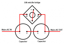
Much simpler, so I am just running one side of the AC (-) thru this?
Would you know what size Capacitors are needed and Rectifier? Parts list I can take to Radioshack etc..
Thanks for you help
Much simpler, so I am just running one side of the AC (-) thru this?
Would you know what size Capacitors are needed and Rectifier? Parts list I can take to Radioshack etc..
Thanks for you help
"Much simpler, so I am just running one side of the AC (-) thru this"
Correct ... it inserts in the neutral line
You need to keep an eye on the bridge as it could get very hot and may require a sink
When I added the cost of putting one together with a premium outlet and IEC plus a heavy aluminium case ... I just bought 2 PS Audio Humbuster III at $150 each instead
Some of the valuve's of the caps I've seen are 2200uF and 3300uF at 16v
4700uF at 35v and if you look at the attached you'll see Bryston uses the circuit in some of their amps with 33000uF 6V caps
Sorry I can’t make a recommendation .. it was my own indecisions that led me to take the safe route and buy the HBIII’s
Attachments
Thanks for all your help, I think this may be a little beyond my abilities and if to do it right is going to cost $100, I might be better off just purchasing a PS Audio Humbuster III. Again appreciate you sharing your experience with this problem.
can you post the ps audio humbuster schematic"Much simpler, so I am just running one side of the AC (-) thru this"
Correct ... it inserts in the neutral line
You need to keep an eye on the bridge as it could get very hot and may require a sink
When I added the cost of putting one together with a premium outlet and IEC plus a heavy aluminium case ... I just bought 2 PS Audio Humbuster III at $150 each instead
Some of the valuve's of the caps I've seen are 2200uF and 3300uF at 16v
4700uF at 35v and if you look at the attached you'll see Bryston uses the circuit in some of their amps with 33000uF 6V caps
Sorry I can’t make a recommendation .. it was my own indecisions that led me to take the safe route and buy the HBIII’s
Much, an enormous amount of very much, has be posted about the way these AC Mains supplies can have a net DC component in the distorted AC waveform.
Similar amounts of explanation have been given on why some transformers are susceptible to this form of waveform distortion and why the DC blocker can come to the aid of these susceptible transformers.
And yet I still see all the crap being repeated on what the DC blocker is NOT capable of doing.
The capacitors are the working element in the DC blocker.
The diodes are an overload bypass.To remove DC you need some ...... capacitors,
- Status
- Not open for further replies.
- Home
- Design & Build
- Construction Tips
- humbuster schematic

