I rebuilt a vintage amp and noticed that while its noise performance is good, one channel has significantly more residual hum than the other.
With the two channels' inputs grounded:
Channel A @ speaker terminals: 1.22mv RMS (60hz) = -87dB vs full power
Channel B @ speaker terminals: 0.399mv RMS (60hz) = -98dB vs full power
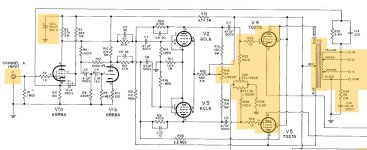
So I began comparing the two channels using my PicoScope's spectrum analyzer to see where along the audio chain the two channels' performance diverged. I found that the problem starts at the anodes of V4 and V5. There is no sign of it beforehand. If anything, the bad channel's hum performance is slightly better than the other channel's until the anodes of V4 and V5. Here's what I found at the anodes:
Channel A 60Hz hum: -35.8 /-38.5 dBv (V4 / V5 @ pin 3)
Channel B 60Hzhum: -52.1 /-51.2 dBv (V9 / V10 @ pin 3)
Pretty huge difference.
I triple checked, and no difference in hum between the channels shows up at the grids, screens, or cathodes of the power tubes, nor at the B+ center tap of the output transformer. And again, at the grids of the power tubes, Channel A's hum is actually slightly lower than Channel B's.
I thought maybe my power tubes were the issue. So I swapped the power tubes between the channels, re-biased, and tested. Exact same result.
I've jiggled and moved the OPT leads. No change.
I jiggled and moved the filament wiring. No change. And surely if they were the source, the hum would appear elsewhere in the output stage. But it only appears from the anodes and forward to the speaker terminals.
edit
With the power tubes removed, the hum remains unchange
**********
Thoughts??
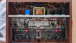
The channel in question is at the left side of the attached pic. Is the hum maybe coming from the speaker terminals' proximity to the mains power? Perhaps coupling between the output transformer and power transformer?
With the two channels' inputs grounded:
Channel A @ speaker terminals: 1.22mv RMS (60hz) = -87dB vs full power
Channel B @ speaker terminals: 0.399mv RMS (60hz) = -98dB vs full power
So I began comparing the two channels using my PicoScope's spectrum analyzer to see where along the audio chain the two channels' performance diverged. I found that the problem starts at the anodes of V4 and V5. There is no sign of it beforehand. If anything, the bad channel's hum performance is slightly better than the other channel's until the anodes of V4 and V5. Here's what I found at the anodes:
Channel A 60Hz hum: -35.8 /-38.5 dBv (V4 / V5 @ pin 3)
Channel B 60Hzhum: -52.1 /-51.2 dBv (V9 / V10 @ pin 3)
Pretty huge difference.
I triple checked, and no difference in hum between the channels shows up at the grids, screens, or cathodes of the power tubes, nor at the B+ center tap of the output transformer. And again, at the grids of the power tubes, Channel A's hum is actually slightly lower than Channel B's.
I thought maybe my power tubes were the issue. So I swapped the power tubes between the channels, re-biased, and tested. Exact same result.
I've jiggled and moved the OPT leads. No change.
I jiggled and moved the filament wiring. No change. And surely if they were the source, the hum would appear elsewhere in the output stage. But it only appears from the anodes and forward to the speaker terminals.
edit
With the power tubes removed, the hum remains unchange
**********
Thoughts??
The channel in question is at the left side of the attached pic. Is the hum maybe coming from the speaker terminals' proximity to the mains power? Perhaps coupling between the output transformer and power transformer?
Attachments
Last edited:
I would swap driver tubes too. Just in case it is a cathode insulation problem.
Also if you leave the power tubes out, could you measure noise? Could be a transformer coupling problem though also could be input stage coupling on one side too.
Also if you leave the power tubes out, could you measure noise? Could be a transformer coupling problem though also could be input stage coupling on one side too.

What amp is it if you don't mind me asking?I rebuilt a vintage amp
jeff
I didn't mention in the original post, but I have channel-swapped the preamp and driver tubes as well. Hum is unchanged.What amp is it if you don't mind me asking?
jeffI would swap driver tubes too. Just in case it is a cathode insulation problem.
I hadn't thought of that. I'll give it a shot. I'm sure everything can handle the boosted voltage for the few seconds it would take to test it.Also if you leave the power tubes out, could you measure noise? Could be a transformer coupling problem though also could be input stage coupling on one side too.
vinylkid58 said:What amp is it if you don't mind me asking?
jeff
It's a Lafayette KT-550
I would swap driver tubes too. Just in case it is a cathode insulation problem.
Also if you leave the power tubes out, could you measure noise? Could be a transformer coupling problem though also could be input stage coupling on one side too.
The hum is unchanged without the power tubes.
Hearinspace said:Why is the capacitor clamp at top left empty?
It's not needed. I made new PCBs for the amp that allowed me to, among other things, move the decoupling caps from the PSU bracket to the PCB.
Did you have a chance to measure hum before the rebuild? Just wondering if something in layout changes could have anything to do with it. Maybe retracing those steps?
Just talking in hopes of nudging your insight.
Nice looking boards and rebuild BTW. far cleaner than the original for sure.
Good Luck !
Just talking in hopes of nudging your insight.
Nice looking boards and rebuild BTW. far cleaner than the original for sure.
Good Luck !
Without the power tubes there shouldn't be any hum at all. He just wrote that in #5. Hence, no need to swap B+ between the channels. Tjhough I never encountered it, I suspect magnetical stray into this output transformer.
Best regards!
Best regards!
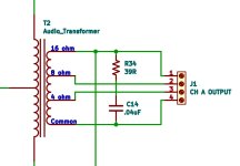
Why would you need to do that? In the schematic you posted? What effect does it have on hum?Have you ground the secondary of output transformer?
Indeed, but there wasn’t one in the picture you posted. Always helpful to say why.The negative feedback loop would not complete without grounding the secondary
Have you ground the secondary of output transformer?
Why would you need to do that? In the schematic you posted? What effect does it have on hum?
I forgot to add it in the schematic. Good catch! But yes. It's grounded. You can see it in the photo: the twisted white/black pair that goes from the speaker terminals to the front end is the feedback (white) and ground (black).
The feedback is grounded at the junction of R1, R0, and the input jack ground.
Is it really 60 Hz? Or 120 Hz?
It's 60Hz (see original post). There is some 120Hz on both channels, but it's at something like -110dB, and it's equal between both channels.
If without the power tubes hum difference does not change, common sense would be to swap +B between channels, the problem is in power supply.
The hum at the center tap of the transformer (B+) and at the screens of the output tubes is very low, and equal in both channels.
If it were a supply issue, I would expect to see hum in the screens and the center tap of the trouble channel, not just at the anodes. Yes? Or am I missing something?
Did you have a chance to measure hum before the rebuild? Just wondering if something in layout changes could have anything to do with it. Maybe retracing those steps?
Just talking in hopes of nudging your insight.
Nice looking boards and rebuild BTW. far cleaner than the original for sure.
Good Luck !
Thanks! Yes, this is quieter than the original. In fact, lab measurements when this was first released in ~1962 pegged the hum at -83dB at full power, and that was done by an actual lab.
I suspect if I had lab gear (and technique), I would find the actaual hum measurement is better than what I'm measuring. My little $100 scope is precise enough for comparing, but not accurate enough to claim an absolute number.
Without the power tubes there shouldn't be any hum at all. He just wrote that in #5. Hence, no need to swap B+ between the channels. Tjhough I never encountered it, I suspect magnetical stray into this output transformer.
Best regards!
That's my thought at this point.
Yes, likely it's induced hum from the power transformer or its wiring into a sensitive part of the circuit, perhaps the OT.
What part of the PT wiring is not symmetric in the chassis?
What part of the PT wiring is not symmetric in the chassis?
Maybe there is magnetic coupling between the power and output transformers, if they are in close proximity to each other. Re-orienting one of the transformers with respect to the other one would fix the problem if that is the cause.I rebuilt a vintage amp and noticed that while its noise performance is good, one channel has significantly more residual hum than the other.
With the two channels' inputs grounded:
Channel A @ speaker terminals: 1.22mv RMS (60hz) = -87dB vs full power
Channel B @ speaker terminals: 0.399mv RMS (60hz) = -98dB vs full power
So I began comparing the two channels using my PicoScope's spectrum analyzer to see where along the audio chain the two channels' performance diverged. I found that the problem starts at the anodes of V4 and V5. There is no sign of it beforehand. If anything, the bad channel's hum performance is slightly better than the other channel's until the anodes of V4 and V5. Here's what I found at the anodes:
Channel A 60Hz hum: -35.8 /-38.5 dBv (V4 / V5 @ pin 3)
Channel B 60Hzhum: -52.1 /-51.2 dBv (V9 / V10 @ pin 3)
Pretty huge difference.
I triple checked, and no difference in hum between the channels shows up at the grids, screens, or cathodes of the power tubes, nor at the B+ center tap of the output transformer. And again, at the grids of the power tubes, Channel A's hum is actually slightly lower than Channel B's.
I thought maybe my power tubes were the issue. So I swapped the power tubes between the channels, re-biased, and tested. Exact same result.
I've jiggled and moved the OPT leads. No change.
I jiggled and moved the filament wiring. No change. And surely if they were the source, the hum would appear elsewhere in the output stage. But it only appears from the anodes and forward to the speaker terminals.
edit
With the power tubes removed, the hum remains unchange
**********
Thoughts??
The channel in question is at the left side of the attached pic. Is the hum maybe coming from the speaker terminals' proximity to the mains power? Perhaps coupling between the output transformer and power transformer?
With the two channels' inputs grounded:
Channel A @ speaker terminals: 1.22mv RMS (60hz) = -87dB vs full power
Channel B @ speaker terminals: 0.399mv RMS (60hz) = -98dB vs full power
Is this really ''hum'' or is it ripple on the scope? I don't think I've ever actually heard this level of signal on the speaker terminals as ''hum.''
- Home
- Amplifiers
- Tubes / Valves
- Hum Appears at Power Tube Anodes