Hi,
well, I got my dirty little fingers on a nice mint HP8596E Spectrum Analyzer, unfortunately it has a problem, the CRT remains blank as if there is a problem with the HV power supply. When I plug a monitor into the video output, I get good display on the video monitor so the analyzer itself works fine.
So I am looking for a service manual or at least a schematic for this unit, but can't find it.
Can someone help me ?
You won't find any schematic for the monitor section. It was made by an OEM for HP. I reverse-engineer, fix, rebuild, calibrate and test obsolete CRT monitors like the ones on your HP analyzer but new CRTs are getting scarce.
Here's a NIB last one, no affiliation -> Omni Vision LP0615E3Y most 8590 series Display | eBay
Here's a NIB last one, no affiliation -> Omni Vision LP0615E3Y most 8590 series Display | eBay
Last edited:
Thanks ej25awd for offering help. In the meantime I did manage to get the schematic of the CRT assembly. Someone pointed me to it, so I am giving it a try before scrapping the entire unit.
Soja, I have been working on this pesky CRT assembly for the HP analyzer all day. I replaced all electrolytic capacitors. The once removed measured all well below rated capacitance and for my taste with too high ESR.
The CRT display seems crippled, it is very dim and at intermittent times it flares up to full brightness. I probed around and measured voltages. The +60V rail measured +75V and the -200V rail only measures -142V. So I replaced D3 and R76 but no change. I guess the flyback transformer is done.🙁
The CRT display seems crippled, it is very dim and at intermittent times it flares up to full brightness. I probed around and measured voltages. The +60V rail measured +75V and the -200V rail only measures -142V. So I replaced D3 and R76 but no change. I guess the flyback transformer is done.🙁
Attachments
before condemning the flyback you should check the HV if you have a suitable probe. There may also be an issue with the brightness and contrast controls. The pots can fail and give weird problems. You should be able to check those voltages at the connector on the base of the CRT.
There are retrofit kits for some HP analyzers that fit LCD displays and it should be a pretty simple retrofit on that unit as well if you can find one or figure it out.
Or use an old desktop LCD. The plus would be a much bigger display that's easier to see.
There are retrofit kits for some HP analyzers that fit LCD displays and it should be a pretty simple retrofit on that unit as well if you can find one or figure it out.
Or use an old desktop LCD. The plus would be a much bigger display that's easier to see.
Unfortunately I don't have measurement capability for such high voltages and I don't really feel comfortable diving in this deep. If there is something with the HV, it's the transformer fault again anyway. I did measure the 600V rail, it also measures slightly lower with about 560V. I did check the front panel brightness pot, it seems fine, measures 100k. I also measured the master bright Pot, seems fine too. Also I measured the voltages on the the voltage divider around the master bright Pot R52, they seem quite a bit off to my calculations since the -200V is this far off. The resistors measure all good.
This leads me to believe the FLB Transformer is no good anymore.
I would entertain the idea of putting an LCD upgrade into it, alto this might be more involved and perhaps a bit pricey.
This leads me to believe the FLB Transformer is no good anymore.
I would entertain the idea of putting an LCD upgrade into it, alto this might be more involved and perhaps a bit pricey.
The heater filament in the CRT could have failed too... That's easy to test once its unplugged, but I'd worry about the EHT half-life after power-down.
The CRT display seems crippled, it is very dim and at intermittent times it flares up to full brightness. I probed around and measured voltages. The +60V rail measured +75V and the -200V rail only measures -142V. So I replaced D3 and R76 but no change. I guess the flyback transformer is done.🙁
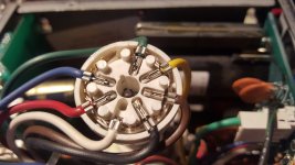
Check that the socket hasn't arc'd over. Not uncommon when dirt and grime get inside.
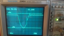
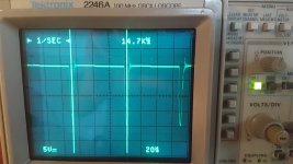
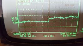
Well, poking around a bit more, this is what I got. The socket seems surprisingly clean. The filament measures about 49 Ohm. and the signal waveform on the 200V winding (pin 8 FLBT DCA) looks like this, getting about 210Vpp. I am not experienced with CRT and tube stuff, so I have no clue if this is a decent waveform but I do not like the hiccup on the rising edge.
I also pulled R75 to see if the -200V rail normalizes, but nope still short at -140V. R75 and C49 measure good.
What do you guys think ?
I also pulled R75 to see if the -200V rail normalizes, but nope still short at -140V. R75 and C49 measure good.
What do you guys think ?
Attachments

There are retrofit kits for some HP analyzers that fit LCD displays and it should be a pretty simple retrofit on that unit as well if you can find one or figure it out.
That would definitely be my choice. You can find the retrofit kits on eBay. The 85xx-series of spectrum analyzers are quite nice. I have one that covers 30 Hz to 2.1 GHz. I use it quite a bit to verify that my headphone amps aren't oscillating at some ungodly frequency. I use opamps and buffers with 200-300 MHz bandwidth, so "stuff" can happen.
Just be super careful about NEVER getting DC on the input of the spec an. It fries the input stage.
Tom
Hi Tom,
Thanks, I have a look for it, alto for now I try to avoid spending too much money. I'd be ok with it if I could manage to get the CRT working again. Yes, I hear ya, thanks for pointing out the input delicacy, I am actually not intending to use this analyzer for audio work but for RF. I think this analyzer goes down to only 85dB or so. Not good quite enough for audio spectrum. If I ever use it for audio, I will make up, a little coupling capacitor gadget for it.
Well, for using such op-amps, perhaps the bandwidth could be limited to lets say 10MHz.😀 Make sure you have a good look at the datasheet, some op-amps absolutely do not like a ground-plane underneath. Yep, been there...😀
Well, I am not having much luck with this CRT module. I replaced R53, R50, R51, R86 on the brightness circuit except R52 the master pot itself. I increased C36 to 220nF. This seems to tame down the up-flaring a bit. The voltage on the R52 wiper is constant when I get these flare ups. I get these brightness flareups also with the front panel pot disconnected. The 600V rail is constant at 567V. I also replaced R27, R55, R59, R76. I found that during a flareup the voltage drop over the 1k R59 increases from about 50mV to about 350mV. I had a meter directly on the CRT pin 1 and there the voltage changes from about -50V to +30V during a flareup. Overall the image is not really sharp as I would expect it, the focus dial R28 is dialed all the way to the positive side.
Unfortunately I can not verify the HV coming from the FLB. I am running out of ideas, could the CRT itself be bad ?
Unfortunately I can not verify the HV coming from the FLB. I am running out of ideas, could the CRT itself be bad ?
Well, I did more measurements.
Rails with CRT connected with CRT disconnected
+600V +568V +570V
-200V -138V -139V
+60V +70V +70V
Then just for good measure I replaced R80 also, now 200 Ohm.
And I managed to take video of the event. Please note, during these flareups focus sharpens right up for brief period of time as seen in the lower left on the screen in the video. Also, for some reason, when I do connect the remote brightness pot, these flareups seem to occur more often and more pronounced, it seems. This video was taken with the remote pot connected.
Video download link: (Will be deleted on 14 October, 2019)
WeTransfer
Those symptoms look like an HV cap in the grid/cathode circuit may be intermittently breaking down. The focus bias and the cathode grid all interact. It could even be contamination around the CRT socket. Lots to check. There may be a tutorial on CRT troubleshooting on the web somewhere.
Many Thanks for your help.
Yes, contamination was suggested, I looked for it, but so far the socket seems clean, no indication of arcing. It appears the socket can not be opened without damage, so I have not attempted to look inside the CRT socket.
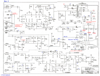
Can you have a look at the schematic and advise which caps you might think could cause this ?
Yes, contamination was suggested, I looked for it, but so far the socket seems clean, no indication of arcing. It appears the socket can not be opened without damage, so I have not attempted to look inside the CRT socket.
Can you have a look at the schematic and advise which caps you might think could cause this ?
Attachments
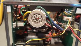
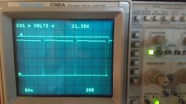
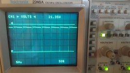
So I opened up the CRT socket, found nothing indicating trouble. I removed each contact re-soldered it and gently pushed the contact forks to have more bite on the CRT pins when engaging. This seems to have helped noticeably with image sharpness. However the flareups still persist. I had the scope probe 10:1 connected to Pin 2 CRT to view the video signal during a flareup. This signal remains absolutely stable. as seen in the image below. Then I had the scope probe 10:1 connected to Pin 1 CRT, there I can observe an substantial instability during these flareup events, as seen in the video linked below. Average DC is rising.
Videos Will be deleted on 14 October, 2019
WeTransfer
.
Videos Will be deleted on 14 October, 2019
WeTransfer
.
Attachments

Hi kct,
The schematic doesn't render very clearly on my screen. It appears that R59 might connect to C15? But I doubt my guess is correct, as then there would be no path for DC bias to CRT pin 1. Would you clarify for me where the R59 and C15 connections go and the signal names noted on the schematic?
Thanks.
- Home
- Design & Build
- Equipment & Tools
- HP8596E Spectrum Analyzer repair