Maybe I just sorted out probable label and path: Label is "G1" connecting R59, C15, and C35?
If this is correct, can you follow flareup misbehavior back to the collector of Q22 and perhaps to R84 and R82? Be suspicious of C15 breakdown or possible defects in Q22 or nearby passives.
Good luck!
If this is correct, can you follow flareup misbehavior back to the collector of Q22 and perhaps to R84 and R82? Be suspicious of C15 breakdown or possible defects in Q22 or nearby passives.
Good luck!
@BSST
Thanks for offering some help. I think so, C15 connects to R59. At some point I hat C15 lifted from the board to exclude a possible path to positive potential, it is not causing the issue. All Q22 circuit does, is to blank the retrace. So with C15 lifted, the issue persists. Yes, I think this label says G1. The schematic is not of good quality, I use the layout as well to trace things and be sure what I am looking at.
I am more and more leaning towards perhaps an issue with the HV. Today I am going to attempt to measure it.
I think measuring HV is probably a good idea. Do you know expected voltage? I was going to suggest making your own HV divider with with a string of resistors so you could see dynamic behavior on your scope.
Sporadic failure of C35 might be a possible fault.
I think having C15 removed is an excellent, perhaps insightful experiment in conjunction with this: Do you know the value of the remote Brighness pot? I suspect the pot network has a relatively low resistance compared to R50 (270K). So most of the dynamic G1 waveform should be across R50 with comparatively attenuated waveform at junction of remote Brightness pot wiper, R50, and R53(?) (1 M). If this voltage is relatively constant, but large brightness flare voltage still evident across R50, then there may may be an intermittent short within the CRT grid. 🙁 I hope there's a more benign culprit.
Good luck.
I doubt its the HV. That potential doesn't change that fast. It could be an internal breakdown between the cathode and G1. Also it could be a breakdown between the filament and the cathode.
Have you checked/changed C36? if that node shorts the CRT will get much brighter.
Do you get a full screen raster at any setting of the brightness control?
Can you look at the voltage between the cathode and G1 during the flash? That would require a differential measurement. G1 should not change unless there is a flashover inside the CRT. This is a common problem and I remember adding components to deal with that in CRTs. But that was 40 years ago for computer displays and its all pretty fuzzy now.
Another insight from fuzzy memory-
Is the image the right size but dim? Does it change when flashing?
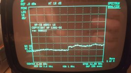
If the HV is low the image will expand substantially, if its about right the HV is probably right.
Is the image the right size but dim? Does it change when flashing?
If the HV is low the image will expand substantially, if its about right the HV is probably right.
Looking at the video the HV is fine. The G! voltage would be the culprit. You could put another cap .01UF 1 Kv directly to pin 1 to see if it stabilized.
@BSST,
well, by disconnecting C15 I verified that the vertical sync circuit has nothing to do with the problem of these random flareups. I measured the remote brightness pot, it is 100k. Yes, I just got back from resistor shopping, I bought 100 pcs. 2.2M. I am not sure how high of a voltage to expect there, I am guessing 15kV at most. I am about to fabricate this voltage divider but having slept over this, I came up with a theory I am going to verify first before messing with the high voltage stuff. See further below what I mean.
@1audio,
Yes, I checked C36, it measures good on my meter, altho this means nothing at higher voltage. However the voltage on C36 is not that high. if I remember correctly the voltage there is anywhere between +50V and - 80V or so at most when things are stable for the moment.
I'd say the image size remains about the same during these flareups.
I totally agree, G1 looks very suspicious as I have measured there the instability while elsewhere there is little to none instability that stands out in any way. And here we are on to something I believe. For fun and gigles, I put 220nF 250V capacitors to ground on both sides of R50. This seems to tame these flareups right down and gives almost a constant brightness but without much control over it. With the Sharpness I could kind of live with altho I would want the image to be sharp.
Please bear with me here for a second as I explain my theory. I checked on ebay, and found two such CRT monitors offered, both seem to have noticeable screen burn-in's as bad as mine. Sure this could just mean operators cranked up the brightness with little regard to CRT life, but I suspect a design flaw here. I believe many of these CRT of this type suffer from the same issue. Someone suggested to look for contamination that could offer a creep path for high voltage I looked the CRT socket as many have found problems there, at least on some TV. So at the CRT socket life is good, but what about on the other end of the connection ?
The thing that kept me up at night is that it flares up in brightness not down, this means G1 gets more positive. Confirmed as seen in the video I took of G1. Everything is stable at some DC on G1 and then suddenly I see the G1 rise erratically just to settle back down to about the same DC for a while and then this spectacle repeats.
I suspect intermittent creep currents but not inside the CRT tube, but outside of it.
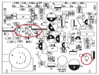
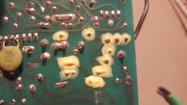
Looking at the PCB diagram, G1 (GRN) is located right next to G2 (RED) on this PCB, perhaps separated by about 4mm or even less than that. Other CRT connection are clustered in very close proximity there as well, except Yellow, the video signal on the Cathode. This signal is far away on the opposite side of the board and well clear of anything nearby.
So G2 (RED) sitting neatly at a healthy 567V just 4 mm away from G1 (GRN)....😀
Hmmmm....
I am not sure what the Layout guy was thinking when squishing these signals this tightly together and on top of that running a jumper J1 (G1) half across the board when he could have conveniently have G1 (GRN) located at the other end of J1. Saving himself the trouble of putting the jumper, using up board space while easing up the CRT connection congestion.
Hmmmm....
Must have been a bad Monday, I guess....
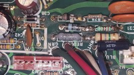
My theory is that, I might have creep right there between GRN and RED, either on the component side or on the bottom. I suspect on the component side, its very crowded an the wires leading to the CRT socket have a little contact crimped to them which is then soldered into the board.
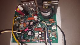
To confirm this theory I will dismantle this entire assembly to get good access to clean this board thoroughly, I will then apply something to add insulation to these connections, I am thinking using my wife's finger nail lacquer or perhaps some silicone. Then after reassembly I have a strong feeling the flareups will be gone.
The more I look at this exceptionally terrible layout design, the more I lean towards my theory.
What do you guys think ?
Does this sound reasonable for a theory ?
well, by disconnecting C15 I verified that the vertical sync circuit has nothing to do with the problem of these random flareups. I measured the remote brightness pot, it is 100k. Yes, I just got back from resistor shopping, I bought 100 pcs. 2.2M. I am not sure how high of a voltage to expect there, I am guessing 15kV at most. I am about to fabricate this voltage divider but having slept over this, I came up with a theory I am going to verify first before messing with the high voltage stuff. See further below what I mean.
@1audio,
Yes, I checked C36, it measures good on my meter, altho this means nothing at higher voltage. However the voltage on C36 is not that high. if I remember correctly the voltage there is anywhere between +50V and - 80V or so at most when things are stable for the moment.
I'd say the image size remains about the same during these flareups.
I totally agree, G1 looks very suspicious as I have measured there the instability while elsewhere there is little to none instability that stands out in any way. And here we are on to something I believe. For fun and gigles, I put 220nF 250V capacitors to ground on both sides of R50. This seems to tame these flareups right down and gives almost a constant brightness but without much control over it. With the Sharpness I could kind of live with altho I would want the image to be sharp.
Please bear with me here for a second as I explain my theory. I checked on ebay, and found two such CRT monitors offered, both seem to have noticeable screen burn-in's as bad as mine. Sure this could just mean operators cranked up the brightness with little regard to CRT life, but I suspect a design flaw here. I believe many of these CRT of this type suffer from the same issue. Someone suggested to look for contamination that could offer a creep path for high voltage I looked the CRT socket as many have found problems there, at least on some TV. So at the CRT socket life is good, but what about on the other end of the connection ?
The thing that kept me up at night is that it flares up in brightness not down, this means G1 gets more positive. Confirmed as seen in the video I took of G1. Everything is stable at some DC on G1 and then suddenly I see the G1 rise erratically just to settle back down to about the same DC for a while and then this spectacle repeats.
I suspect intermittent creep currents but not inside the CRT tube, but outside of it.
Looking at the PCB diagram, G1 (GRN) is located right next to G2 (RED) on this PCB, perhaps separated by about 4mm or even less than that. Other CRT connection are clustered in very close proximity there as well, except Yellow, the video signal on the Cathode. This signal is far away on the opposite side of the board and well clear of anything nearby.
So G2 (RED) sitting neatly at a healthy 567V just 4 mm away from G1 (GRN)....😀
Hmmmm....
I am not sure what the Layout guy was thinking when squishing these signals this tightly together and on top of that running a jumper J1 (G1) half across the board when he could have conveniently have G1 (GRN) located at the other end of J1. Saving himself the trouble of putting the jumper, using up board space while easing up the CRT connection congestion.
Hmmmm....
Must have been a bad Monday, I guess....
My theory is that, I might have creep right there between GRN and RED, either on the component side or on the bottom. I suspect on the component side, its very crowded an the wires leading to the CRT socket have a little contact crimped to them which is then soldered into the board.
To confirm this theory I will dismantle this entire assembly to get good access to clean this board thoroughly, I will then apply something to add insulation to these connections, I am thinking using my wife's finger nail lacquer or perhaps some silicone. Then after reassembly I have a strong feeling the flareups will be gone.
The more I look at this exceptionally terrible layout design, the more I lean towards my theory.
What do you guys think ?
Does this sound reasonable for a theory ?
Attachments
Last edited:
Maybe you could just move the circuitry off the board between the brightness control and the CRT socket. It is a resistor and a cap all of which are non critical for parasitics.
The PCB could easily have an issue either internally or on a surface you can't see. If G2 is stable and the cathode is pretty stable then the current to move G1 comes from somewhere else and the PCB could be the culprit.
Those monitors are not built to the same standards as the rest of the instrument. It was a pretty cutthroat business with huge cost down pressure.
Long term the LCD replacement would be the best move but a simple fix would be a good value. Are there connections for an external monitor? Maybe worthwhile to add a VGA connector with H,V and video connected as a backup.
Your theory may well be correct.
To narrow the possibilities, I'd adopt Demian's approach and "air wire" a 270K resistor between the the remote pot wiper and CRT pin 1 so that the board circuitry is unused and disconnected. I wouldn't bother adding the capacitors--- the 270K would be the only part in the grid circuit. If the resulting raster still flares, the defect is likely a grid to other tube element intermittent. With luck, maybe defect will prove to be on the PCB.
To narrow the possibilities, I'd adopt Demian's approach and "air wire" a 270K resistor between the the remote pot wiper and CRT pin 1 so that the board circuitry is unused and disconnected. I wouldn't bother adding the capacitors--- the 270K would be the only part in the grid circuit. If the resulting raster still flares, the defect is likely a grid to other tube element intermittent. With luck, maybe defect will prove to be on the PCB.
it is curious that a 270K resistor in series with a 1K resistor and a small cap would call out a 1/2W 1K resistor. Some detail is not shown in the schematic. Maybe there are issues around G1 and significant currents?
This link has more stuff than I could ever possibly remember about fixing "TVs" Notes on the Troubleshooting and Repair of Television Sets and lots of hood ideas.
This link has more stuff than I could ever possibly remember about fixing "TVs" Notes on the Troubleshooting and Repair of Television Sets and lots of hood ideas.
It's hard to imagine large grid currents in normal operation, but maybe the designers were intending to cover the possibility of a shorted grid. Q22 appears to generate 50V switching on its collector. Maybe R50 is sized for smoke avoidance? 😉
Actually HV to grid arcs are not unknown and those can smoke parts easily.
If you were local I have the HV probes etc. for looking at CRT stuff.
If you were local I have the HV probes etc. for looking at CRT stuff.
Well, in short, my theory did not work out. The flareups still persists. 🙁
I took this thing apart again and throughly cleaned the PCBs, noticing they were not properly cleaned when manufactured, virtually every solder joint had some flux residue even on the component side.
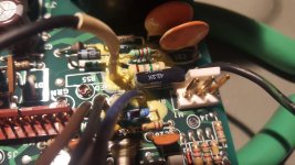
I rewired G1 and G2 such that they are separated well from each other, I also put nail lacquer on the higher voltage part leads and solder joints.
So now I am back to square one. I guess now I have no further excuse to avoid messing with the HV. Altho I don't think this is a HV problem.
Yes, I also wondered why would they do a 270k with a 1k in series, while the 1k is a fat one. It does not make sense to me at all at this point. For the time been, I put a 2k and another 2k in series, so I have now 270k + 2k + 2k. In between the 2k's I put a 220nF to ground. This tames the flareups a little bit and slows things down altho it does nothing about the absolute brightness variation. Brightness is all over the place, from very dim to somewhat normal and then super ultra bright so much so I worry I could burn something out. For brief periods the image is quite pleasant and acceptable.
I tried to locate a CRT but no luck. It could be the company is long gone.
BWL 779009 MTI Monitronics
Coming to the realization there is not much more I could do, sucks.
Next thing to do, might be taking some money and sniping a CRT assembly of ebay.
.
I took this thing apart again and throughly cleaned the PCBs, noticing they were not properly cleaned when manufactured, virtually every solder joint had some flux residue even on the component side.
I rewired G1 and G2 such that they are separated well from each other, I also put nail lacquer on the higher voltage part leads and solder joints.
So now I am back to square one. I guess now I have no further excuse to avoid messing with the HV. Altho I don't think this is a HV problem.
Yes, I also wondered why would they do a 270k with a 1k in series, while the 1k is a fat one. It does not make sense to me at all at this point. For the time been, I put a 2k and another 2k in series, so I have now 270k + 2k + 2k. In between the 2k's I put a 220nF to ground. This tames the flareups a little bit and slows things down altho it does nothing about the absolute brightness variation. Brightness is all over the place, from very dim to somewhat normal and then super ultra bright so much so I worry I could burn something out. For brief periods the image is quite pleasant and acceptable.
I tried to locate a CRT but no luck. It could be the company is long gone.
BWL 779009 MTI Monitronics
Coming to the realization there is not much more I could do, sucks.
Next thing to do, might be taking some money and sniping a CRT assembly of ebay.
.
Attachments
The CRT business is very dead. You may find one but it would be chance.
An LCD may be a viable option. Look for one with 12V supply and H,V and video in. That was the standard for a long time.
Or as I suggested if you don't need portability patching it to an LCD monitor would not be too difficult. Tie it to a VGA cable. short the RGB together for white for video and H and V for sync and many monitors (older ones especially) will figure out the sync etc. and give you a nice large picture.
Yeah, I have been looking at that. I was thinking getting a Coby CX-TV6 5" 480i CRT TV and gut it and squish it into this analyzer. Altho doing such a hack to this fine instrument would hurt me. I also, don't like having an external monitor. All the newer style mini TV's are all LCD based with 16:9 format. They do not seem to be suitable or would fit.
This really sucks.
This really sucks.
This may be a possible display 5 inch 800*480 TFT LCD HD Screen Monitor for Car Rear View Reverse Backup Camera 657385102920 | eBay supports RGB and its $18.
I may get one or three for my vintage videobridges.
I may get one or three for my vintage videobridges.
I just found this: HP/Agilent 8590 CRT Display unit, tested, 8591,8592,8593,8594,8595,8596 | eBay it may be the quickest and cheapest fix.
I also confirmed it already has an NTSC video out on the back that could run an internal monitor.
Thanks, I guess I am going with the CRT display. Got to get approval from my finance minister, tho. 😀
- Home
- Design & Build
- Equipment & Tools
- HP8596E Spectrum Analyzer repair