I just did a comparison test using an HP 400F wideband ac voltmeter.
Both 339A had the osc/buffer replaced for lowest thd. But one had those and all other IC's/opamps replaced.
The almost stock noise measured 2.4mV or about -50dB level from the monitor out with analyzer input shorted. About the same as you measure and show with QA400. The one with all IC changed measured .25mV (-66dB). When I limited the BW being measured to 100KHz (via switch on 400F), the noise dropped to -70dB re 1v ref.
However, when all the filters where selected, added about 4dB more noise to - 46dB to the nearly stock unit.
With the 339A which had all opamp replaced and had all its filters in, the noise was also -46dB. That is a 20dB increase due to the filters. They now dominate as a noise source when used.
THx-RNMarsh
Last edited:
The filters are Sallen-Key multi-pole, and I have always found them to be very noisy, regardless of amp type used. I believe the results would be better with a simple RC low-pass, even though the cut-off wouldn't be as sharp. Another thing on my 339 to-do list.
Sync, if I read you right, the meter pegged when you connected to the monitor output -- I assume with the QA400. I think that was caused by a grounding issue, maybe back to your computer... Try moving the 339's ground switch to the right-side (or to the center if it is on the right-side). I had the same problem connecting my EMU 0204 -- something got back into the meter circuit and upset the reading, even though I got good data from the mon. out..
Sync, if I read you right, the meter pegged when you connected to the monitor output -- I assume with the QA400. I think that was caused by a grounding issue, maybe back to your computer... Try moving the 339's ground switch to the right-side (or to the center if it is on the right-side). I had the same problem connecting my EMU 0204 -- something got back into the meter circuit and upset the reading, even though I got good data from the mon. out..
For the noise measurements -- The ground switch was to the right (floating from chassis).
[Center position (signal common connected to chassis ground) was much noisier.]
Anyone make a quiet quad opamp?
THx-RNMarsh
[Center position (signal common connected to chassis ground) was much noisier.]
Anyone make a quiet quad opamp?
THx-RNMarsh
Last edited:
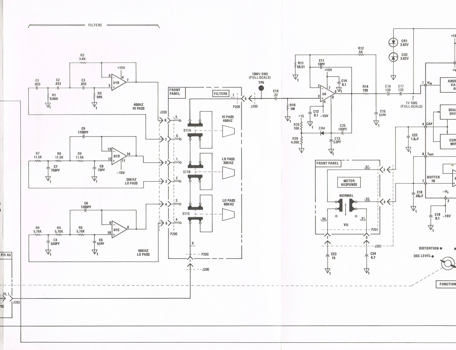
If I look at the schematic for the filters.
Wondering if we can replace sallen-key with
toggle switch with pot or rehostat
to dial it in if need be?
Maybe some type of crossover that is used for
3 way loudspeaker but with higher frequencies.
The HP339a analyzer would be in the midrange
driver position but with higher frequency roll off.
How steep are the slopes on the current filters?
RichEEM, plugging anything into the Monitor
output causes the meter to move beyond full range
even with nothing connected to it, i.e., banana to BNC
that is open./non connected.
@Sync -- very strange behavior, which leads me to think that there is major instability in the meter/output circuitry -- and rapid bursts of oscillation would certainly cause a lot of spiky noise at the output, so I think you still have troubleshooting work to do.
RE the filter circuits, avoid "speaker type crossover" circuits which are LCR types -- the Ls would need to be heavily shielded magnetically, which is not practical. You could use gyrators to replace the Ls with opamps, but that is a pain.
I would keep the quad opamp, using one of the quieter types, say the quad LME49710, and just make interstage RC LP filters with a slightly higher -3dB point than the one indicated by the switch on the panel -- say 40kHz for the 30k, 100kHz for the 80k -- or not; a little more in-band rolloff won't compromise the readings. I would also like a 10kHz filter.
But the real issue is the 400Hz HP -- for that a sharper cutoff is really a good thing in order to supress hum and 1/f noise, but I think a two-stage RC is do-able for -12dB/octave roll off.
But, IMHO, right now that's all looking too far ahead -- get the existing filters working, because they do provide essential filtering for use with the built-in metering. 2014 state of the art won't help you until the 1980 state of the art is working well. Remember, the 339A is a very good, high sensitivity, wideband TRMS AC voltmeter -- one of the best around.
RichEEM,
That is really funny. It's about the most observant
and most relevant statement that I've read in a long time.
"2014 state of the art won't help you until
the 1980 state of the art is working well." --Dick Moore
That is really funny. It's about the most observant
and most relevant statement that I've read in a long time.
"2014 state of the art won't help you until
the 1980 state of the art is working well." --Dick Moore
I just tried a direct replacement of TL074 with LME49740 quad opamps. Little difference in noise change..... use of filters still increases noise significantly. So, yes, maybe interstage RC filters will do it better.
THx-RNMarsh
THx-RNMarsh
At 3.6 pA/rthz it's not going to do well at higher impedance.
Try an OPA1644 jfet 5nV/rtHz. You'll need a breakout board.
Try an OPA1644 jfet 5nV/rtHz. You'll need a breakout board.
The TL074 is not a *terrible* amp. I'm still pretty sure that it's the filter topology that causes the problems.
The Shibasoku 725 uses 3rd order Sallen key too. I don't see a rise in noise when engaging those filters.
That's a good point -- I wonder about parts values; maybe Shiba did a low Z implementation, since distortion doesn't matter after the notch filtering and post notch gain stages... What amps did they use, David?
I just substituted in a OPA4131 and there was still no improvement. Looking more and more like high R's are a problem.
Possibly topology, too.
THx-RNMarsh
Possibly topology, too.
THx-RNMarsh
I just plugged in the J200 connector and got the following:
Jumper -13.2 dB
w/J200 -13.5 dB
80kHz -18 dB
+30kHz -18.5 to -19 dB
+400Hz slammed full right.
This still has the socketed LME49740 installed for the filters.
Richard, what did it do with the OPA1654 installed?
Jumper -13.2 dB
w/J200 -13.5 dB
80kHz -18 dB
+30kHz -18.5 to -19 dB
+400Hz slammed full right.
This still has the socketed LME49740 installed for the filters.
Richard, what did it do with the OPA1654 installed?
Guys what is the gain of the post amp?
Shibasoku was very careful about gain distribution in the 725. They put the filter behind a gain of 36dB max.
The original op amps in the 725 were TL072 and HA5115 for the 750kHz.
Now they are OPA2134 and LT1468 for the 750kHz LP filters.
I'd have to look again at the HP but it matters in which order the filter are arranged.
the 400Hz HP should come first. HP followed by LP.
If distortion doesn't matter then put the filter on the post side of the last amplifier.
Noise will be gone. SNR you know.
Last edited:
Yes the 725B/C uses lower value resistors and higher value caps in there filters.
The 750kHz filter uses near 600 ohm resistors.
The 750kHz filter uses near 600 ohm resistors.
Here's partial A2 schematic:
David, I guess it depends on what you mean by "first".
If we look at the schematic coming in from J203 (lower left)
the first filter is the 80kHz, followed by the 30kHz, then 400Hz.
The feed from J203 is the Auto Set Level when engaged
If not,Osc or Input level from the voltmeter attenuator
(10mV RMS full scale) from a2U13 feeds the circuit.
When Rel Level is selected then the signal goes through
U12 (everyone favorite LM741) and the 5K rel adjust pot
on the front panel.
Y'all have a great week, and keep warm.
Cheers,
From the output perspective, the First filter that feeds TP5
and U4
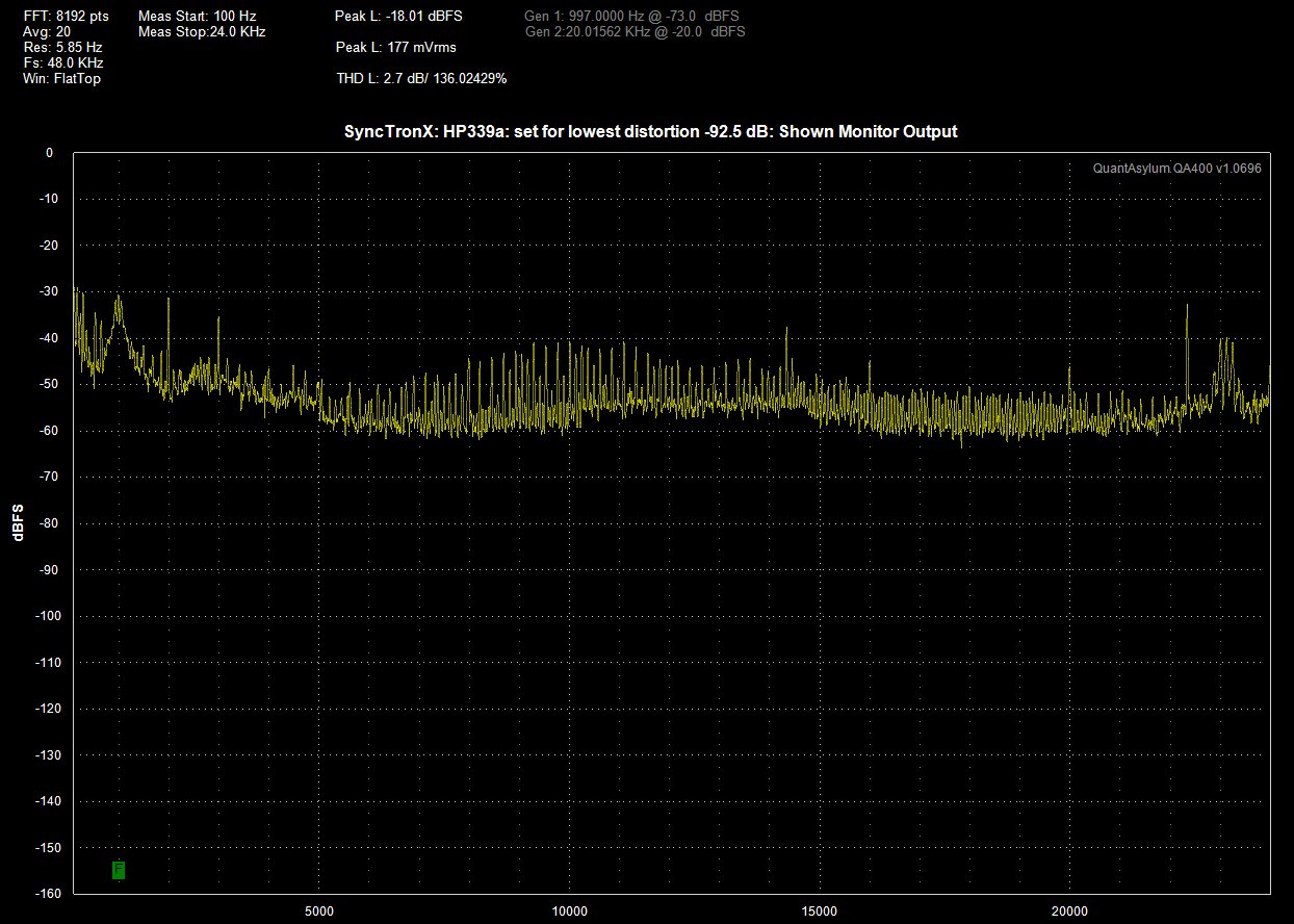
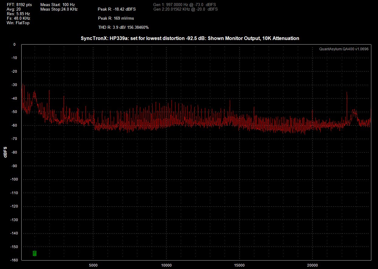
That will have to wait for some JFETs.Yes, thats what it seems to me, also. Adjust the osc level on the pcb to get a null... below -92.5dB if you can. Can be very touchy if you didnt replace that control with a ten-turn. Then see what it reads. Final adjust is on the analyzer portion..... null is on the vertical plug-in pcb at the rear.
THx-RNMarsh
I have the substitute board in for now until I undo all the changes
I made to the pullout board as that part of the project was abandoned.
I took the JFET from it to put next to the A1 oscillator.
Patience is a hard thing to learn and sometimes we don't have a choice.
Last edited:
The filters can be rerouted to the output of the output amp U4 instead of being at its input. .
Run the wire from J203 to j200/TP5. That bypasses the filters. Then reroute the U4 out to filter input at P200/7. [remove connection from J200 to P200] This brings you into the 400Hz filter first. The filter output at P200/0 goes the the output on the front panel.
-RNM
Run the wire from J203 to j200/TP5. That bypasses the filters. Then reroute the U4 out to filter input at P200/7. [remove connection from J200 to P200] This brings you into the 400Hz filter first. The filter output at P200/0 goes the the output on the front panel.
-RNM
- Home
- Design & Build
- Equipment & Tools
- HP339A distortion analyser