RNMarsh,
Do you know how the VP-7722A measures the 2nd, 3rd, and so on harmonics when the appropriate button is pressed? I'm assuming some filtering to get to the frequency of interest?
VP-7722 have a Dsp processor to handle /measure the 2H, 3H ..... I think.
No special Filter expect Notch,400Hz LP .... in 7722 when I look inside of it.
Last edited:
David,
Yes, that is where my HP339a takes a dive.
TP1: 9.45Vp
TP3: 9Vdc, from 45mv - 117mV pp
TP4: 80mVpp, 4mVdc
TP5: .92 Vdc,
TP6: .001 Vpp, 0Vdc
Tp8: -.461 Vdc, .02 Vac
Yes, that is where my HP339a takes a dive.
TP1: 9.45Vp
TP3: 9Vdc, from 45mv - 117mV pp
TP4: 80mVpp, 4mVdc
TP5: .92 Vdc,
TP6: .001 Vpp, 0Vdc
Tp8: -.461 Vdc, .02 Vac
VP-7722 have a Dsp processor to handle /measure the 2H, 3H ..... I think.
No special Filter expect Notch,400Hz LP .... in 7722 when I look inside of it.
Thanks sky2city
@ RNMarsh,
Have you removed C14~C17, R78 arround U3?
yes... removed.
-RNM
RNMarsh,
Do you know how the VP-7722A measures the 2nd, 3rd, and so on harmonics when the appropriate button is pressed? I'm assuming some filtering to get to the frequency of interest?
No. Dont know how only the selected individual harmonic gets displayed.
-RNM
Developing pics from the lab was quite slow but here they finally:
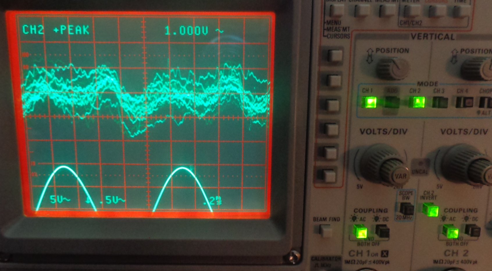
These was the output from the oscillator to the distortionan analyzer
input section. The final nasty harmonic distortion taken from the Monitor
ouput. Do can someone Richard, Davada perhaps post some similar pics
to see how properly functioning HP339a looks on scope compared to this
one? Many folks I'm sure would appreciate it. It will also be good to have
some documented screens do the DIYer that follow will have a trail with
some crumbs.....
Here is the next one: Showing the since wave at TP1 just off the oscillator.
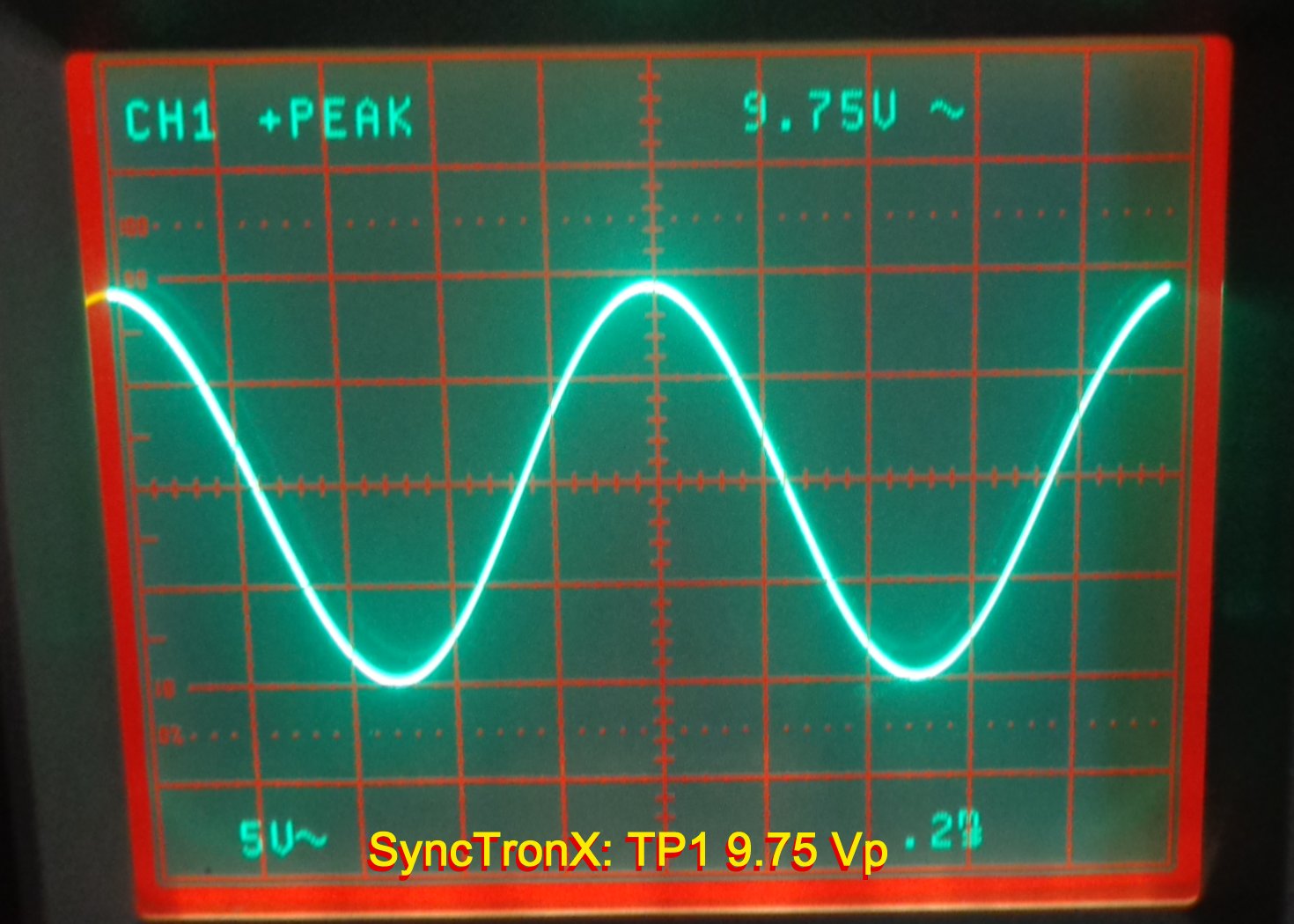
Following that, this:
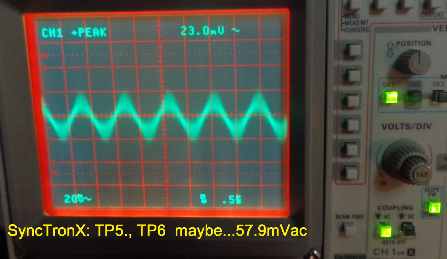
Perhaps mislabled, should actually be TP3, right at 9.0 VDC as it should be.
Then there where problem started to rear the head. TP5, TP6 were both 23 - 30 mV ac at the time as shown. Later some how they changed slightly,m which was strange. The other componant was the checking the DC voltages....93 Vdc where they should have been8Vdc on TP5.
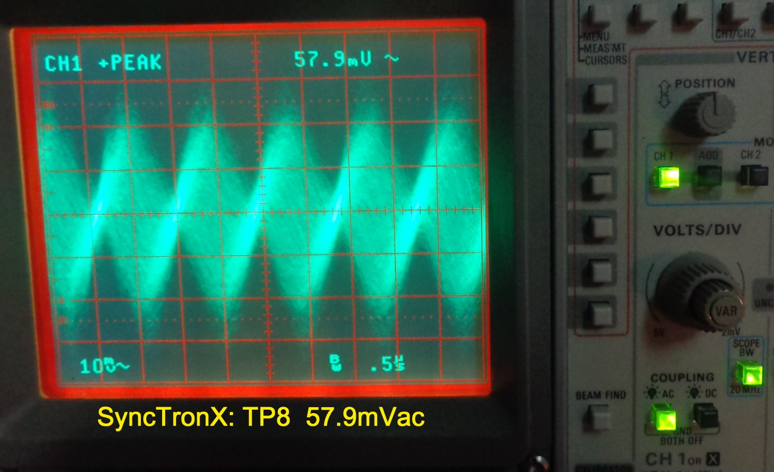
And these:
TP8 just off the main oscillator and JFET should be smooth and clearly
defined to -.461Vdc
So will one of you gentleman take the time to show your scope pics of the same
Test Point voltages. This will be a really big help for anyting troubleshoot their HP339a meters in the future. We've got the screwed up one, now lets see what we should be seeing.
cheers y'all.
ow
These was the output from the oscillator to the distortionan analyzer
input section. The final nasty harmonic distortion taken from the Monitor
ouput. Do can someone Richard, Davada perhaps post some similar pics
to see how properly functioning HP339a looks on scope compared to this
one? Many folks I'm sure would appreciate it. It will also be good to have
some documented screens do the DIYer that follow will have a trail with
some crumbs.....
Here is the next one: Showing the since wave at TP1 just off the oscillator.
Following that, this:
Perhaps mislabled, should actually be TP3, right at 9.0 VDC as it should be.
Then there where problem started to rear the head. TP5, TP6 were both 23 - 30 mV ac at the time as shown. Later some how they changed slightly,m which was strange. The other componant was the checking the DC voltages....93 Vdc where they should have been8Vdc on TP5.
And these:
TP8 just off the main oscillator and JFET should be smooth and clearly
defined to -.461Vdc
So will one of you gentleman take the time to show your scope pics of the same
Test Point voltages. This will be a really big help for anyting troubleshoot their HP339a meters in the future. We've got the screwed up one, now lets see what we should be seeing.
cheers y'all.
ow
Last edited:

Maybe Demian can answer this for me. As I made my voltage divider,
10K for Positive coupled to 1K for ground, We got the same general plot
as above. However when we added a 10K resistor to the other 10 K,
the pre (no more headroom) clipping...went away.
So we had 20K tied to the QA400 Positive while we still kept
the 1k to the negative on the QA400. It cleaned up nicely.
So I don't know if I was over driving the QA400?
Or
Was the additional resistance enough to load the oscillator
and keep it from clipping?
Developing pics from the lab was quite slow but here they finally:
These was the output from the oscillator to the distortionan analyzer
input section. The final nasty harmonic distortion taken from the Monitor
ouput. Do can someone Richard, Davada perhaps post some similar pics
to see how properly functioning HP339a looks on scope compared to this
one? Many folks I'm sure would appreciate it. It will also be good to have
some documented screens do the DIYer that follow will have a trail with
some crumbs.....
Here is the next one: Showing the since wave at TP1 just off the oscillator.
Following that, this:
Perhaps mislabled, should actually be TP3, right at 9.0 VDC as it should be.
Then there where problem started to rear the head. TP5, TP6 were both 23 - 30 mV ac at the time as shown. Later some how they changed slightly,m which was strange. The other componant was the checking the DC voltages....93 Vdc where they should have been8Vdc on TP5.
And these:
TP8 just off the main oscillator and JFET should be smooth and clearly
defined to -.461Vdc
So will one of you gentleman take the time to show your scope pics of the same
Test Point voltages. This will be a really big help for anyting troubleshoot their HP339a meters in the future. We've got the screwed up one, now lets see what we should be seeing.
cheers y'all.
ow
There is some oscillations and or noise showing up in the last two pics. This is your problem.
It's in the others just can't see it as well.
What do you read on the THD meter when you put the sine wave output to the analyzer input? THD level??
THx-RNMarsh
THx-RNMarsh
Richard,
On the HP339a, 1kHz, 3Volt,
Frequency set to CAL, Osc Level full CW from the OSC output,
into the Distortion Analyzer with 600 ohm terminator,
function set to Distortion,
Distortion Range set on - 70 dB
the meter indicates -7 dB
for -77 dB total.
without the 600 ohm terminator
Distortion Range set on -80 dB
the meter indicates -3.2 dB
for -83.2 dB total.
@Sync -- I spritzed my switches with LPS-1, which has always worked flawlessly for such things for me, and they all came back to life. I think you should clean every switch in your 339.
@RichEEM, I"ve cleaned them once, but that doesn't mean I can't
clean them it again.
AND
I know I have a can of LPS-1 around here somewhere.
Zo, ein spritz heir, ein spritz da,
denn ein slug Weisse Mischen Ja ga na ya. ; )
clean them it again.
AND
I know I have a can of LPS-1 around here somewhere.
Zo, ein spritz heir, ein spritz da,
denn ein slug Weisse Mischen Ja ga na ya. ; )
Bummer
No LPS-1...ti is hiding from me.
I did go back through it with DeOxit
D100, D5, then air while working the switch
followed by MCL 100.
When engaged it stops the meter.
No LPS-1...ti is hiding from me.
I did go back through it with DeOxit
D100, D5, then air while working the switch
followed by MCL 100.
When engaged it stops the meter.
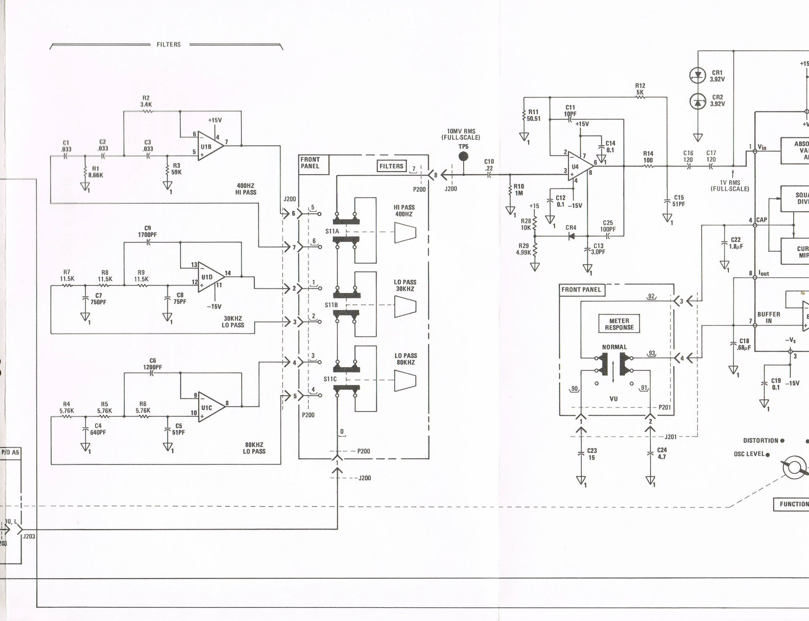
But, engaging the 400 Hz switch does put 11V dc on
A2 TP5. It's right next to the front panel just below the
switches. The other two switches don't do this.
Then there could be something wrong with the quad
opamp that is in there in A2, U1-B.
OR
The socket that it is in.
A2 TP5. It's right next to the front panel just below the
switches. The other two switches don't do this.
Then there could be something wrong with the quad
opamp that is in there in A2, U1-B.
OR
The socket that it is in.
But, engaging the 400 Hz switch does put 11V dc on
A2 TP5. It's right next to the front panel just below the
switches. The other two switches don't do this.
Then there could be something wrong with the quad
opamp that is in there in A2, U1-B.
OR
The socket that it is in.
No way you should get 11Vdc after switching in the 400Hz filter. But you already know that.
Either the op amp is toast or a pin is floating. What at the output of the filter when the 400Hz switch is out?
As I remember no audio on either the in or the out from the 400 Hz filter on that 339. Symptoms point at a dead IC or a solder bridge somewhere.
The high distortion on the oscillator looks like feedthrough from the AGC. There is more junk on the agc pin of the fet than I would expect to see. There is stuff on the fast recovery line that I expect should not be there if its in range.
I think a J108-J110 would work fine in that application and far cheaper than the original part n a metal can.
Here's the schematic:
The only source of positive voltage there is right
on the 400Hz opamp U1 B.
I'm guessing. I'll have to check it on the back side
of the board.
The only source of positive voltage there is right
on the 400Hz opamp U1 B.
I'm guessing. I'll have to check it on the back side
of the board.
Demian, You live! That's good, glad you didn't get driven
over by cellphonetalkingdrivingfools.
David, when it is out there was nothing on the line.
strangely there was only the 11Vdc when I checked
why the meter pegged to nothing. I figured I'd check
to see what if there was DC.
Now when out after about 30 engage cycles there is a
residual .20Vdc.
Funny thing working through this thing almost makes me
think I'm working on real physics--imagine that.
Last edited:
- Home
- Design & Build
- Equipment & Tools
- HP339A distortion analyser