Here is what I understand how to do notch, cals and phase:
External Source, 1V, 1kHz into Distortion Analyzer.
HP339a under test. knob settings:
Oscillator Level - OFF
Frequency Vernier 1kHz (should have no effect.
Frequency knobs (1 x 1K)
Meter Knobs:
Input Range = 1 V
Distortion Range = 0
Input/GND Select = DIS AN float (30V Max)
Filters = OUT
Meter Response = Norm
Function = Distortion Analyzer
1. Set FFT to A3 TP3
a. Set input 1V 1kHz on A3 TP4 (reading from this test point?)
or place signal on A3 TP4.
b. Calibrate Notch (for lowest notch level in -dB)
c. Calibrate Phase (not sure how to do phase?)
2. Connect FFT to A4 TP1
a. adjust InputBalance for min hash and harmonic(dbV & THD from QA400?)
b. repeat Step 1 (Step 1, 1a, 1b, 1c?)
3. Connect to TP3. Not sure what to do next.
I couldn't find this proceedure in the manual.
Doesn't mean it isn't there but didn't find it.
manual has the outputs at the MONITOR
for me, that is problematic.
Clarification would be appreciated.
Note: my set point on the A3TP4 reading is different
on the DUT HP339a. 1V, 1kHz into distortion analyzer
results in a A3TP4 reading of 3.174V AC on my Meter.
or roughly the manual's set point of 3.162 +- .04 for Meter,
LED, AUTO LEVEL etc.
"I couldn't find this proceedure in the manual."
No you won't fund it in the manual. These are my procedures.
"results in a A3TP4 reading of 3.174V AC on my Meter."
This is correct for a stock unit.
If you read the mods from the oscillator thread you will see I rescaled the input level to the notch filter to 1Vrms for a 1Vrms input to the analyzer. This not a necessary step unless you want this mod for tapping the notch filter output.
RichEEM,
I agree. It was during the Cal procedure that I noticed the elephant ears.
This was from identifying and tuning the voltages around
the meter, their pots, the 1/3 and Full Deflection of the meter.
It generally meets specs but there is still some kind of funny business
that I've not been able to diagnose.
From what I identified, those elephant ears are before the Meter and
it's output. It is there when I place the FFT on A3 TP3 and get the
meter working within range.
There are two areas that I have problems with
that is tweaking the subsystems and the more detailed offset
set points for setting the harmonics in the HP339a.
I"ll have to spend some more time on the review of
the manual.
Also I have to find the harmonics that Demian suggested I
try to identify too.
There are still issuses around the 400 Hz filter.
A1U2 quad opamp is screwy.
I'll start back and look at the power suppy with
the FFT QA400 and see what it looks like.
I can't see those harmonic distortions on the scope.
I can see when it is screwed up bad on the scope.
The other thing I need is for David to find out
what all he did to get his A4 board working with
the LT1468. I need to insure I have the right
cap in the right place. I undid most of the stuff
on that board but a couple of little things.
I'll plag board #2 into A4. That will isolate a problem
in the HP339a unit or on the A4 board.
First I'll check power supply rails then the pin 6 of
A1U1. Then go back to A1U2 Quad OpAmp look
at harmonics, and scope.
Hopefully I can work some more this weekend
and in between life.
Appreciate everyone's thoughts and input. : )
Sync return the A4 board to it original state. I don't how many times I have stressed to you thet you need to do these mode from a clean slate. The mods must be done one at a time and evaluated before going on to another. otherwise you end up as you are, confused by not knowing what's causing what. Do the repairs first then the mods. If the repairs are not successful then don't do any mods at all.
A4U1 goes crazy at -50 dB on pin six. -40dB it's with the
supply noise or background noise.
I thought at fist it was because I removed two of the zeners
on the A4U1 board and lost them or they got lost when the
container of parts fell over. These are the little CR1 and CR7
3.92 V zeners. Wonder if any old zener will work...
i've got some 8V, 9V and 12V ones I guess I can sub in
and see.
A4 board almost is to original state.
Missed a few. Things. Only difference is with the LT1468 and
200 ohm resistor. And the feedback cap.
I do have the 1uf cap from 47pf on C47 or C8.
I think was changed too. were replaced.
I thought those procedures
were for adjusting the null, balance etc.
I have pages of notes from the Oscillator thread,
hence the all the mods that I've done and undone.
I'll get there. I think I have 2000 more posts to
go through. I started with post 1 originally then
started taking notes.
then tried to find post numbers as page number numbers change.
That is hard to reach in there as pin 1 & 4 side is right at the corner of
the gound casing.
Last edited:
LOL
Richard, you think? From your side?
Imagine what it's like on my side...on the receiving end!
Richard, you think? From your side?
Imagine what it's like on my side...on the receiving end!
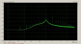
This what my 339A look like on the monitor.
I haven't touch this analyzer in two years and had a bit of soldering to do. I left it in slightly dissembled state.Four hours later here it is. I need to cal the A4 board better and the filters are causing trouble. It's actually not the filters but the filter switches that are causing noise.
If I work the switches for a while it kind of starts working again.
Attachments
A4U1 has one purpose only: to drive the balanced modulators used as phase detectors (that tune the notch filter to the fundamental) with square waves, and the value of those zeners is important -- not just any zener will do. Along with the high gain of U1, the zeners are signal clippers that make fast and clean pulses for the detectors to do their jobs. You really must find those zeners and use them -- these really are critical components. I don't remember that David changed those parts, wouldn't need to. The extra gain he added using the 200 ohm R can be beneficial to getting a deeper notch, as we've recently discussed. I'll see if I can find a part number for those zeners -- they are special...
David, is that the distortion range knob set to zero?
I've got the part numbers from the manual
1902 - 1335, the 3.92 zener diode.
I would imagine these were probably
matched parts with ultra low Tc.
Looks pretty good, that is my goal too.
As typically happens, I just get set up to
do something then my little girl needs something,
wakes up, grabs something, etc. or life happens
...then sometime later I try again or where ever I left off....
it doesn't always match up correctly.
Walking the plank would be easier.
Keel hauling, well that would be like a whole 'nuther country.
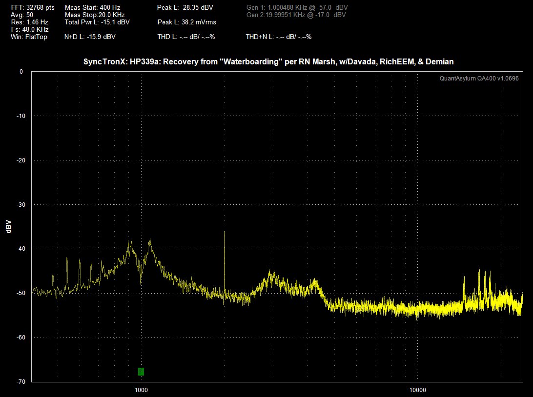
For those following along I've posted parts of the schematic.
You should be able to click to a full size image.


You should be able to click to a full size image.
But then maybe not.
So here are the images:
http://www.diyaudio.com/forums/gallery/showphoto.php/photo/11933
Also in my blog, for anyone using the QA400, I put up a menu list of the
soft switches/buttons for folks to reference.
So here are the images:
http://www.diyaudio.com/forums/gallery/showphoto.php/photo/11933
Also in my blog, for anyone using the QA400, I put up a menu list of the
soft switches/buttons for folks to reference.
David, is that the distortion range knob set to zero?
I've got the part numbers from the manual
1902 - 1335, the 3.92 zener diode.
I would imagine these were probably
matched parts with ultra low Tc.
Looks pretty good, that is my goal too.
As typically happens, I just get set up to
do something then my little girl needs something,
wakes up, grabs something, etc. or life happens
...then sometime later I try again or where ever I left off....
it doesn't always match up correctly.
Walking the plank would be easier.
Keel hauling, well that would be like a whole 'nuther country.
No it's not 0. It-s -80dB. Zero on the scale of ARTA is -80dBV
In the manual HP put selected beside there stock number if the part was anything special.
This includes matched sets. If there is a generic number then it doesn't matter if they're matched. These zeners have to fast.
The modulators operate with input voltages in the low mV, Typically =<15mV.
This includes matched sets. If there is a generic number then it doesn't matter if they're matched. These zeners have to fast.
The modulators operate with input voltages in the low mV, Typically =<15mV.
Last edited:
After I looked at it again, I removed some more of the parts
for the recommended mods that were abandoned.
It is working again with an extremal oscillator.
I took my measurements from the FFT on the monitor output.
I'll go back see what it does with it's own oscillator.
I haven't resolved buffer nor the filter area yet.
Pics at 11. : )
for the recommended mods that were abandoned.
It is working again with an extremal oscillator.
I took my measurements from the FFT on the monitor output.
I'll go back see what it does with it's own oscillator.
I haven't resolved buffer nor the filter area yet.
Pics at 11. : )
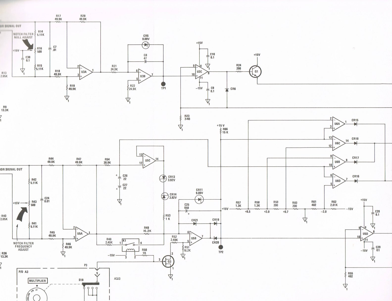
Sync this is with a gain of 1000 on the A4U1 op amp. The offsets from the fundamental are 180Hz. This is the 3rd harmonic of 60Hz. The offsets are hum modulation from the power supply.
Yours is looking better but still has a ways to go.
Switches are causing trouble for this 339A. The mode selector switch is causing signal leakage. I have to work the switch to get it cleared up. The leakage is strong enough to cause the final gain stage before the RMS detector to clip. When this happens the distortion on the monitor port goes way up. The 80 kHz filter is unusable. It completely undoes the 400 Hz filter's effectiveness. It will take some digging to figure out what the problem is there. But unless the switches are working properly then diagnostics are impossible.
Attachments
Sync -- I checked my HP cross-ref for the 3.92V zeners, no luck -- these likely were made specifically by, or for, HP and there are no JEDEC equivalents that I can find.
RichEEM,
Thanks for checking.
Getting it under control...SLOWLY.
They might turn up or if found way later,
they could have been tossed who knows : (
Making headway however slowly.
Thanks for checking.
Getting it under control...SLOWLY.
They might turn up or if found way later,
they could have been tossed who knows : (
Making headway however slowly.
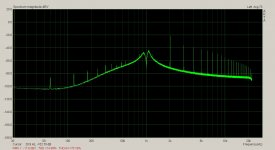
The water just keeps pouring on me just when I thought it was
through.
NOPE
Will all the unchanges...the problem is still present.
I discovered it when I plugged the DUTs own oscillator back
into the Distortion Input ...same Elephant ears.
At lease I know the oscillator input is making the problem
and not the analyzer section by itself.
through.
NOPE
Will all the unchanges...the problem is still present.
I discovered it when I plugged the DUTs own oscillator back
into the Distortion Input ...same Elephant ears.
At lease I know the oscillator input is making the problem
and not the analyzer section by itself.
Starting at the beginning.
A1 TP3
DC voltage is spec 9.1or9.2 Vdc.
AC voltage is hi at 130Vp-p. Spec = 45mVp-p
A1 PT4
DC = .003 - .005 Vdc.
AC = >150mVp-p. Spec = 75mVp-p
A1 TP1
AC= 19.25 Vac p-p.
Replaced CR14 and C24. Didn't make much difference.
Wondering if I should just replace the Diodes in CR2,CR3, CR4
and see if a difference is noted. That would rule out leakage
of those parts. I could also see if the resistors around those
parts drifted or just replace with less noisy parts as I think I have
some. But then where does it end?
I can just see me next year at this time,
replacing my "last" hi dollar, low noise passive.
David will tell me to replace the components with originals.
RichEEM would explain the value and theory of what I just accomplished.
Demian strategizes for me to look at each part with the FFT and hacking in experimental sub sections.
Richard will come up with some additional procs for lowering distortion.
I shall stand before my esteemed colleagues and proclaim:
"Franken-analyzer, Franken-analyzer IT LIVES!
You have taught me, but AYE have given Franken-analyzer LIFE.
::::: Loud thunder clap is heard just out side your doors ::::::::::
To be Continued....
Last edited:
- Home
- Design & Build
- Equipment & Tools
- HP339A distortion analyser