I'm sorry. I know you are doing your best effort to make a nice useful instrument. Its just struck me in a funny way because I know it is easy to make the instrument not work. But that only happened when I went too far with changing things.
I wasnt laughing at you but at my own experience of doing the same thing a few times. I just never put that part (the failures) in the forum.
If you do something and the instrument doesnt work correctly any more .. undo what you last did.
THx-RNMarsh
I wasnt laughing at you but at my own experience of doing the same thing a few times. I just never put that part (the failures) in the forum.
If you do something and the instrument doesnt work correctly any more .. undo what you last did.
THx-RNMarsh
Last edited:
Will get back on it when I get a chance. Hopefully later today. Thanks - David.
Richard, That is what David said, that you went through it too and I guess we
all have the moments of WTF?
Teachable moments is what they are.
And
They are important. Failure of the Narrows bridge, what we learned.
Also, during the Soviet era, they never publicized their failure of burning
up their capsule with the O2 rich environment, had they, we'd have out
Apollo Astronauts still.
The other thing I learned especially when I studied under the Jesuits at Bellarmine,
was that during math we'd all get up and do problems on the board a couple of times
a week.
I carried this over with my teaching of math to middle schoolers. I explained to them
that get up and do the problems and don't worry about making mistakes, you'll make them.
the important thing was to learn from them and go forward from it.
And, to not make fun of the other kids when they make a mistake. Because if you do,
I guarantee you'll be up here and it will happen to you.
The other thing I found, was to remind the students that when they went to take the
tests, they would be fine, because where is the pressure in that? Who was watching?
No one. So they could just go through everything because where is the pressure?
Doing the problems on the board in front of me and your class mates is pressure!
It worked. I had kids come up to me at walley world, telling me how much they
learned and how fun is was for them to be in AP Math class in High School as
freshman doing better then the seniors who've been there for 3 years. 🙂
@David,How much modding have you done with the analyzer?
I've done what I've posted with pics above. That is the
A1U1 - LT1468 and components
A1U2 - LME49740 Quad OpAmp
A1U3 - OPS134
Compensation removed
and the 10K level pot replaced.
I'll just scan my Schematic with notes.
I haven't put another 100uf cap in series with R52 yet
nor have I bypassed it.
A4 error Detector Circuit
Then I did your mods listed in post #996,
A4U1 - LT1468
R1 = 200 ohm
R2 w/12 pf feedback cap.
100K to 10K resistors.
10K to 1K resistors.
A4U4 10K pot on Balanced demodulator.
Not Yet Done.
for A4U1 for that board, maybe I should scrape pin 6 trace
and put 100 ohms across it.
However, currently I've put a different A4 board
in with/out the A4 changes. This is from another
HP339a that I got for parts.
Maybe part of the problem is getting the null too deep?
Maybe not, just thinking here.
Also on the HF balance, the last part of the calibration
with the 60K ohm and 600 ohm resistor at input,
I couldn't get the adjustable capacitor to do anything.
No matter how I turned it.
OKay so the changes are just to the A4 board. Leave that board for now. I went too far with that one and lost the wide tracking. That board won't cause your problem.
The 339a will oscillate if the input is open and the level sensitivity is high and scale set to -80dB FS. Put a 600 ohm load on the input and see if that clears it up.
The 339a will oscillate if the input is open and the level sensitivity is high and scale set to -80dB FS. Put a 600 ohm load on the input and see if that clears it up.
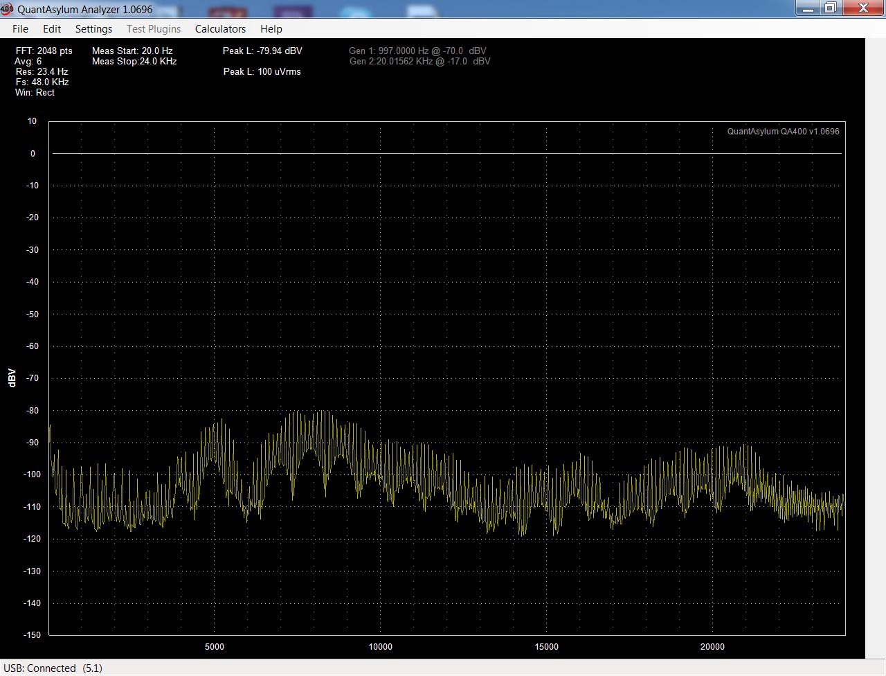
From what I can tell by looking,
the buffer amp is part of the problem right now.
And then somehow, I have bands that rise up
with distortion in 5 kHz bands, that is -10 dB
above the noise floor.
This seems to be imprinting and I'm not sure what causes it.
The power supply isn't so hot and regulation is off about .2 V.
The oscillator power supply seems worse than the Meter Circuit.
7
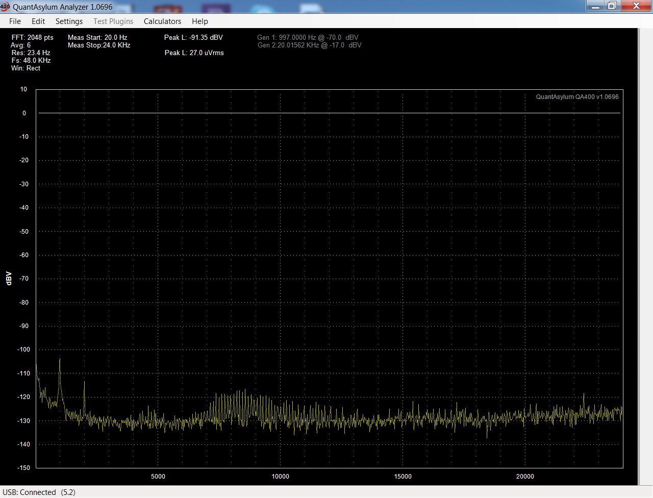
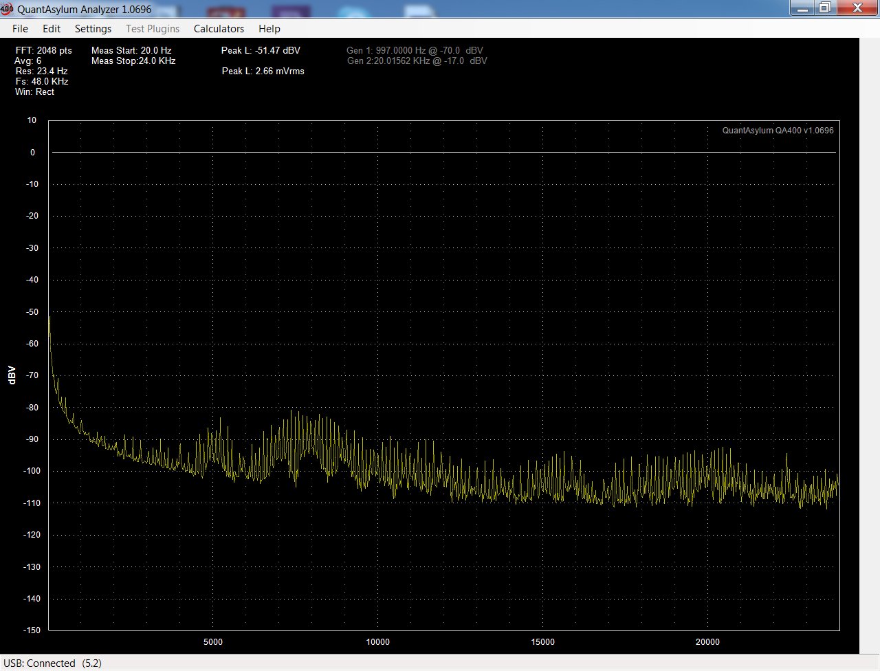
Here is band 10dB higher:

On A3 Lo, A2 TP1, A5, TP502:
Here is noise on A3 Hi:
Here is the Buffer Amp, TP3, TP4, TP6, TP8 are all about the
same as this:
On A3 Lo, A2 TP1, A5, TP502:
Here is noise on A3 Hi:
Here is the Buffer Amp, TP3, TP4, TP6, TP8 are all about the
same as this:
Last edited:
600 Ohms didn't make a difference.
I still think HF Notch Filter
A3C18 but then if Buffer amp ringing?
is contributing somehow, that would
help explain things. Maybe why I couldn't
adjust it after changes.
I still think HF Notch Filter
A3C18 but then if Buffer amp ringing?
is contributing somehow, that would
help explain things. Maybe why I couldn't
adjust it after changes.
Power Supply
Good Side of Power Supply:

Not sure about this one:
Then it gets worse here for the Oscillator circuit TP 303, 304:
Here is the bad stuff:
Good Side of Power Supply:
Not sure about this one:
Then it gets worse here for the Oscillator circuit TP 303, 304:
Here is the bad stuff:
David,
Maybe RichEEM is right, instead of fooling around
with these old regulators, perhaps it's better to stick
some LM317s and LM337s in and go from there.
Scott Wurser might like this simile,
noisy power supply's end up like
bean counters, the screw up
everything all over the place.
Scott, they are invasive,
and not just limited to telecom.
Okay Cheers y'all I appreciate your knowledge and guidance.
I don't find a lot noise from those regulators. The ones in my 339a are quiet. The 317/337 are noisy. You might have a bad regulator. I doubt that the power supply is causing your problems.
Look at the 339a rails on you QA400 decoupled with a 0.1uf series cap. if there a problem there it will be obvious.
Look at the 339a rails on you QA400 decoupled with a 0.1uf series cap. if there a problem there it will be obvious.
I would say it appears more like a measurement problem. Grounding issues most likely. Not a reg IC.
Or, bad solder joint for intermittant noise... maybe joint of a PS cap... resolder,
-RNM
Or, bad solder joint for intermittant noise... maybe joint of a PS cap... resolder,
-RNM
Last edited:
That is supposed to be intermittent noise.
Or
Something is back feeding to it.
It is on the Oscillator +15 volt rail.
I captured it, then on a hunch
I turned the viariable cap for the
H.F. notch tuning. Hmmm, it must
cause an oscillation somewhere on the A3 board...
or perhaps that 1/2 of the PS regulator is oscillating.
Pics at 11
Or
Something is back feeding to it.
It is on the Oscillator +15 volt rail.
I captured it, then on a hunch
I turned the viariable cap for the
H.F. notch tuning. Hmmm, it must
cause an oscillation somewhere on the A3 board...
or perhaps that 1/2 of the PS regulator is oscillating.
Pics at 11
That is supposed to be intermittent noise.
Or
Something is back feeding to it.
It is on the Oscillator +15 volt rail.
I captured it, then on a hunch
I turned the viariable cap for the
H.F. notch tuning. Hmmm, it must
cause an oscillation somewhere on the A3 board...
or perhaps that 1/2 of the PS regulator is oscillating.
Pics at 11
Okay. Well in that case you shouldn't be trying to do mods on a unit that needs repair.
Do the repairs first. If you can't get the part then use the LM317/337 as Dick suggested.
LT has a dual regulator but it is SMT, You would have to use a breakout board to mount it and it won't have the same pin-out.
That is supposed to be intermittent noise.
Or
Something is back feeding to it.
It is on the Oscillator +15 volt rail.
I captured it, then on a hunch
I turned the viariable cap for the
H.F. notch tuning. Hmmm, it must
cause an oscillation somewhere on the A3 board...
or perhaps that 1/2 of the PS regulator is oscillating.
Pics at 11
Disconnect the power supply from the oscillator, load it and see if the noise is there.
How would this noise from an isolated power supply get into the analyzer. You showed a plot of the analyzer alone with elevated noise.
Have you tried the ground switch in a different position? I found it best when the oscillator is floating.
My Bad, it is on the +15 of the Meter.
Here is the POS15 Rail for the Meter
after changing the Function selection:
It also stopped when I turned the adjustable cap on the A3 board.
That Notch Filter HF Adjust Cap A3C18.
That cap also looks like it has head damage to it
on the top. I was very carefull to cover them when
I was cleaning the switches etc.
I'll Try resoldering the Cap leads that I changed etc.
I figured if I banged on them with a
chop stick, if there was a bad or cold
solder joint it would make some noise
that I could see on the QA400.
If that cap shorts then you have very high positive feedback injected in to the notch filter.
The circuit generates a negative Z. I wouldn't worry too much about the calibration for the capacitance cancellation. You will only see an effect near 20kHz. It cancels the input C of the op amp and stray C so the C is not loading the bridged T network. If there is loading effects the 20kHz will droop in level.
You may want to replace it with the spare you have.
Well I got the Distortion again on the +15 V Meter Supply
rail by turning the FUNCTION switch back and forth
and noticing the pulses change with the Relative Adjust
pot rotation. There are pulses on the meters needle.
Hmmm, when the needle is pegged at greater than
minus 20, (zero on the left) then the needle is stable
but the distortion shows on the plot.
Swiching to OSC Level, stops the distortion on the
plot, but the needle pulsates.
Switching to Distortion, Input Level, REL level
all cause the needle to pulsate.
Switching to Osc level Stops pulsate or distortion on plot.
Then I have to switch back and forth a few times for the distortion
to show on the plot again as below.
I'll have to live with the cap the way it is.
I think the spare I bought for parts is better than
this one that I have. This has a lot of wear on the
switches etc.
The Spare has only the Oscillator power supply working.
I think it lived a charmed life as the swiches inside show
no wear on them.
The meter supply is fried in it. Black on the underside of the PS board,
only .7 volts on the +15 Meter Rail. Maybe someone over loaded it or
something. I don't know. It missing Distortion Range and small OSC
Level Pot.
That at least is what I can tell from a cursory look inside it.
Aside from that, I can't see any other obvious damage to it
I got it cheap because of PS is fried.
- Home
- Design & Build
- Equipment & Tools
- HP339A distortion analyser