I looked and couldn't find the order of mods/fixes.
I did find an order frm posts: 1391 - 1404.
Those are for the A1 board and the A4 board.
Then at post #2493 for the Notch Amp A3 U3 opa1461.
Wondering if I can get away with the opa134 there.
either that or work with the little breakout etc,
the way David suggested.
myhrrhleine, thanks for the suggestion. Usually when I try
that stuff I get a wobble then a scrape across what ever I
don't want to scratch. Tape can be your friend I've found.
It is an OPA1641 not 1461. Yes try the OPA134. I used the 1641 because I had some on hand and they're a bit lower noise. Not sure there was much improvement from that.
It is an OPA1641 not 1461. Yes try the OPA134. I used the 1641 because I had some on hand and they're a bit lower noise. Not sure there was much improvement from that.
Great, well I'll put that at the end. Working on the A4 board,
the removable one.
Maybe you can recall the order of the next few things to mod
for this HP339a?
Here is a tip for selecting capacitors for compensation etc. Avoid the PPS caps. The esr is too low. I found these caps to cause parasitic oscillation with the 1468 and others. Even the COG NPO can do this as well. If you find this happening then add a 10 ohm resistor in series with the cap and the op amp will be happy. These new wide band high speed op amps are bit fussy this way. You'll have to discover this by trial and error.
Large stacked type caps tend to act as antennas picking up common mode signals around the circuit. You can get feedback this way usually of the wrong kind. I had to wrap the PP caps in grounded copper foil in my SVO. Try to use the smallest physical size cap you can find even if it means using SMT. The mica and stacked PP caps are about the worst for this because of their size.
Don't blame the op amp.
Great, well I'll put that at the end. Working on the A4 board,
the removable one.
Maybe you can recall the order of the next few things to mod
for this HP339a?
In the end other than the generator I didn't get the distortion down much. I did get the noise at the monitor output down about an order of magnitude. The monitor output then agreed with what I measured at the output of the notch filter. The noise and distortion is somewhat inherent to the design. If the internals ran at 1Vrms instead of 3Vrms then the distortion would be several orders of magnitude lower. But this messes up the scale of the level function by 10dB.
I wouldn't do it again. it's a lot of money for little gain.
The most that can be gained is the work on the oscillator.
IIRC correctly everything --The osc opam gets changed. Also, the jFET has a resistor from drain to gate... that gets changed to a slightly larger value trimmer to adjust for lowest thd. The cap in series with that trimmer gets replaced with a high quality bipolar.
The level control pot gets replaced as it causes higher distortion....might be due to wear on contacts or oxidized parts/resistive material. I used Davids suggested p/n. The main osc thd control is a single turn which is very touchy for null.... replace it with a 20 turn trimmer. No R's and C were changed other than the tant were changed to film or bipolar. Replaced all PS filter caps.
The buffer can or not be replaced. I replaced it. Trimming and adjustment of the osc - I first just used the front panel meter and internal analyzer to adjust osc to a new minimum. If/When you get to the noise/distortion floor of the analyzer, then external analyzer is needed to trim for null. But you are not there yet.
The analyzer -- I swapped pcb of the analyzer section located on the rear panel.... some pcb's didnt work, others worked better/worse. So something on that board makes a difference. I replaced all adjustment controls with multi-turn fims.
On my first 339a I replaced every opamp in the unit. I found the Military or high temp ceramic version of the mulitiplyer IC was able to improve things. It doesnt show on the spec sheets but it is a better part.
I did not do the gain redistribution Dave speaks of -- reduce to 1 volt and then increase gain elsewhere. That works, I am sure.
You can get a meter reading of slightly under .001 thd+n with these changes only.
THx-RNMarsh
Last edited:
Whiskey River....
Gentlemen:
I feel like I'm getting tag teamed.
I got up early to finish and see how things are going.
Finished up all the mods for the A4 board, 10K to 1 K resistors.
100K to 10K resistors. Replacing U1 with LT1468, 10pf feedback
across 200K and change R1 to 200 ohm. Jumping R10, R39. changing
the configuration of the U4 Balanced demodulation input to mirror
U2 with the 10K balanced input. Changed C8 to 1uf. Replaced
680uf electrolytic with new one. Bypassed c26, c27 with a
1uf too.
Putting it on the QA400 and using victor's ultra low distortion Oscillator.
Then I dialed in everything as best as I could using the guidelines on the
Low Distortion Thread post # 996. A4R65 is new 20+turn pot.
Then there is input balance 20+ turn pot at U4, which is a new
input Balance adjustment.
Dialing in for notch and phase, then repeating it on TP3, TP4,
then A4TP1, adjust notch (A4R16) and phase (A4R43) and
for min hash and harmonics (A4R65, A4newBAL),
I got the following:
Trying to use the frequency button on QA400 is useless to me. It won't pick
up on any other signals other than QA400, so what good is that?
Trying to dial in 1Vrms, 1kHz causes QA400 to clip, lights flashing etc.
like the thing is going to blow up?
I guess the Victor's Oscillator is working alright, as it is going to the
HP339a Distortion Input, with the Function = Input Level, it reads
-10dB at the 3V input and -80dB distortion range.
I ended up putting the 20+ turn pots at an angle because they
won't fit just straight up and down with a side adjustment.
I don't know if it is better to build from scratch for keep hacking
away at this baby. It takes a hell of a long time to do the work on
this thing modding it, and all and about 1/2 the stuff I've tried makes
it worse.
Now I have a two oscillators, Victors is small, the HP339a, is BIG.
Richard, would you be kind enough to identify small film caps and
Bi Polar caps I need to purchase? Because what I have isn't working.
The Panasonic Stacked films at .0000 Dissipation factor don't work.
The Film and Foil caps I use don't work either.
There is way too much work in this thing and it doesn't work now.
Where is Willie Nelson when I need him?
Whiskey River Take My Mind.
Any one else doing these mods? Can someone post some pics so I know
how this stuff is supposed to look?
I have to build this stuff on little pieces of perf board, which you can't
see in the pics because it will short out on the board. Modding on
dual sided boards is a challenge. Heck how do they do it with all
the MIL multilayer boards with dedicated ground planes etc.
Oh, they don't. It's pull and replace.
What was I thinking.
Okay, time to be productive, y'all have a nice day and good rest
of the week.
cheers,
On my first 339a I replaced every opamp in the unit. I found the Military or high temp ceramic version of the mulitiplyer IC was able to improve things. It doesnt show on the spec sheets but it is a better part. THx-RNMarsh
I've don't most of those things. Wondering about which parts
are the hi temp ceramic multiplier ICs? Which are they and
where do they go?
You know you are real smart that way with your electronics knowledge.
It must come from experience that you know what to fool with and
what to leave alone.
I kind of dug myself into a hole and will have to figure out how to get
out. I'm pretty good and doing the mods that do the unexpected, it's
just when I get there, I'm so lost, I don't know how to work my way
back out, yet.
Having the right parts is more than 1/2 the battle, it must be like
7/8s.
It's all a matter of perspective. I'm reminded of that by a Marine
named "Chesty" Puller. When his troops came up to him freaking
out telling Col. Puller that they were surrounded and were going
to lose or die. Chesty remarked how they needed to think correctly,
that they were in the ideal situation...
...they could shoot in any direction and kill the enemy!
There is way too much work in this thing and it doesn't work now.
LOL. 🙂 Now it doesn't work? I guess it isnt for the less experienced. I cant help you right now. I am not at my home with all the test equipment. I think we gave good advice in what to do for the least effort after we were done thoroughly going thru it. I summerized that above. Might have missed a thing or two but it really comes down to only a few things to do.
THx-RNMarsh
Richard, that is not nice to laugh at people or the spoiled fruit
of their labors. I feel horrible right now.
And look at that crappy analyzer, it took a very good victor's
low distortion oscillator running through the HP339a analyzer to
look that bad.
We need to develop a "Help I've fallen and I can't get up." for electronics
on DIYAudio.
Maybe, "Nuts, I've followed the mod steps and now nothing works."
Or, "I"m a dip s**t and knew I should have waited for the cliff notes."
On, the bright side I didn't blow up $200 Million in supplies for the
space station.
Now that Hockey has started, I need to brush up on my fore checking
skills. Oh, wait, you mean I have to skate first?
Voice Over: (Most interesting man in the world voice)
But when I skate, I want to skate like this:
Last edited:
Richard, that is not nice to laugh at people or the spoiled fruit
of their labors. I feel horrible right now.
And look at that crappy analyzer, it took a very good victor's
low distortion oscillator running through the HP339a analyzer to
look that bad.
We need to develop a "Help I've fallen and I can't get up." for electronics
on DIYAudio.
Maybe, "Nuts, I've followed the mod steps and now nothing works."
Or, "I"m a dip s**t and knew I should have waited for the cliff notes."
On, the bright side I didn't blow up $200 Million in supplies for the
space station.
Now that Hockey has started, I need to brush up on my fore checking
skills. Oh, wait, you mean I have to skate first?
Sync he's laughing at his own experience. He's been where you are.
I'd like to try and replace that Vernier pot.
Couldn't find a 5 MEG with DPST switch.
Hmmm, I think it is a custom job which means expensive.
I've got other fish to fry first though.
Couldn't find a 5 MEG with DPST switch.
Hmmm, I think it is a custom job which means expensive.
I've got other fish to fry first though.
Last edited:
I swapped out boards with the same result.
So I went back and did a cal procedure for the whole HP339a.
Having the largest problem now with trying to perform the
the High Frequency Calibration.
Eventually I'll revisit the A4 board mods.
So I went back and did a cal procedure for the whole HP339a.
Having the largest problem now with trying to perform the
the High Frequency Calibration.
Eventually I'll revisit the A4 board mods.
Thanks for letting me know, David.
Yeah, I guess y'all have been.
It reminds me of my little girl.
She keeps running into the bottom side of the table
and crys. Then she'll do it all over again.
Glutton for punishment.
She must take after her old man.
Yeah, I guess y'all have been.
It reminds me of my little girl.
She keeps running into the bottom side of the table
and crys. Then she'll do it all over again.
Glutton for punishment.
She must take after her old man.
From your plot it looks to me like a rise in noise from parasitic oscillation. That or ground noise.
You need to clean up your grounding issues before you proceed any further.
Divide and conquer is your friend right now.
Disconnect the signal path but keep the ground path connected. Inject a signal from the 339a oscillator bypassing Victor's osc and see what you have. If the grounding is bad so will be the outcome. If it's bad then remove Victor's osc from the ground path. I've has similar problems with Victor's osc using a notch filter and emu0204. The TL431 is really noisy.
David, when I plugged the other A4 board in and got the sameFrom your plot it looks to me like a rise in noise from parasitic oscillation. That or ground noise.
result, that told me the problem is still in the main board.
So when I did the recal....starting with the oscillator level (was
a + 1.4 volts or something like that) I backed it down
to -.4 V DC, that on A1board pin 8.
At least that cleared up the oscillator.
Reread your other post again about the oscillator, okay
and now understand what you are describing to check for
grounding issues.
Not sure what I will find. I still have problem with the monitor output
and haven't routed to the front panel yet.
Pics at 11.
Last edited:
David, when I plugged the other A4 board in and got the same
result, that told me the problem is still in the main board.
So when I did the recal....starting with the oscillator level (was
a + 1.4 volts or something like that) I backed it down
to -.4 V DC, that on A1board pin 8.
At least that cleared up the oscillator.
Reread your other post again about the oscillator, okay
and now understand what you are describing to check for
grounding issues.
Not sure what I will find. I still have problem with the monitor output
and haven't routed to the front panel yet.
Pics at 11.
Does the problem exist with the 339a osc as the source.
I have have admit I haven't been following this with full attention.
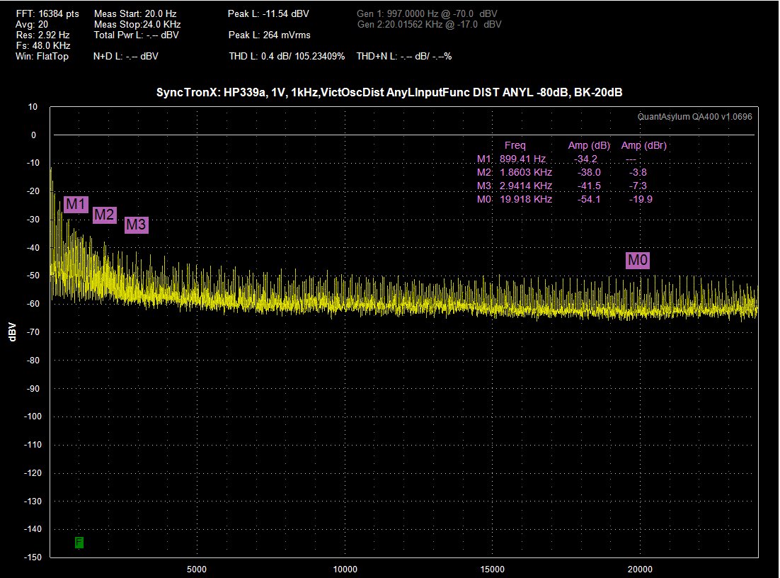
Here is Victors Osc input:
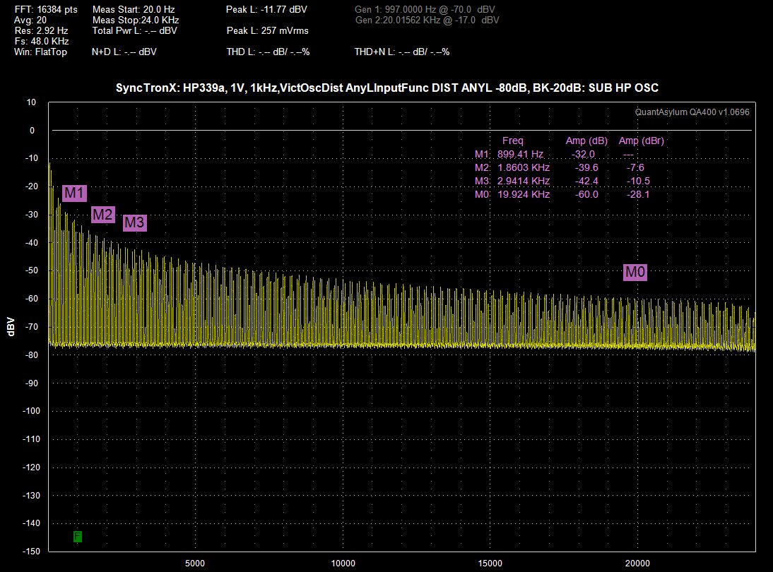
Then Here is the the ground with the HP inserted into the input:
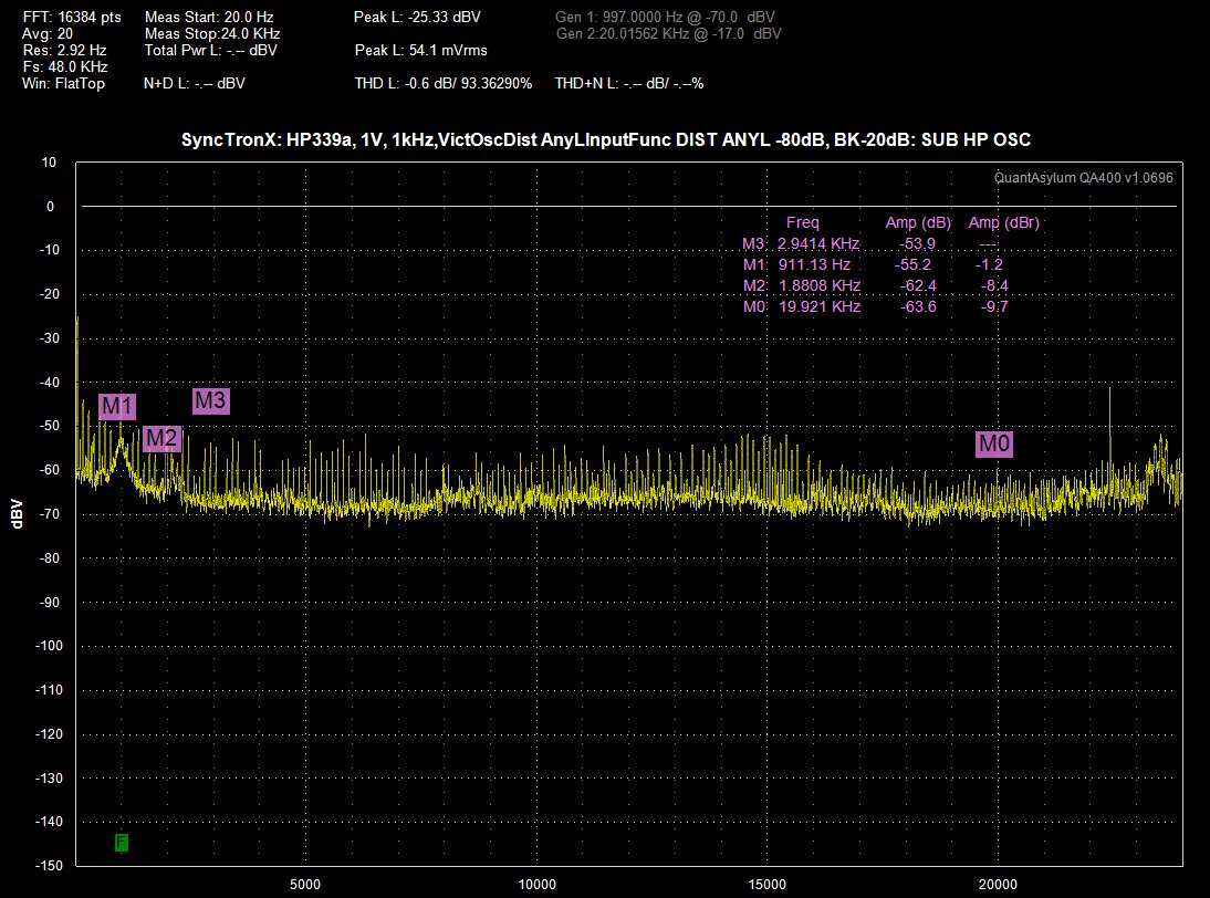
Then, here is the HP oscillator inserted into the Distortion Analyzer:
Here is just the HP:
Then Here is the the ground with the HP inserted into the input:
Then, here is the HP oscillator inserted into the Distortion Analyzer:
Here is just the HP:
Here is Victors Osc input:
Then Here is the the ground with the HP inserted into the input:
Then, here is the HP oscillator inserted into the Distortion Analyzer:
Here is just the HP:
All of the work I did on the 339a was with the QA400. I don't remember the 339a ever looking like that. Indeed you have a problem.
What you need to do is go through each stage of the 339a signal path starting at the input and see where this begins. Use a probe with the QA400. Take the ground from the nearest ground point closest to the section you're probing. You can pull the RCA jumpers to isolate sections. The plot of the 339a by itself looks like parasitic oscillation. Trace this with a scope, no signal input, starting at the the input amplifier.
Last edited:
- Home
- Design & Build
- Equipment & Tools
- HP339A distortion analyser