Hi,
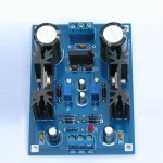
Got a board from ebay delivering +V and -V with LM317/LM337.
The input power is supposed to accept both ACin (3-27V) and DCin (5-40V). ACin connection is obvious, but I cannot get any clear help from the seller regarding how to use DCin to power the board. Is it possible to simply connect DCin to the ACin slots? Or should the DCin be connected somewhere else?
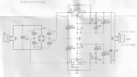
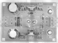
Here below are some pics, hope you can get an idea from the scans.
Thanks in advance for any help.


It would appear so.Is it possible to simply connect DCin to the ACin slots?
Attachments
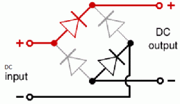
And the polarity doesn't matter, since the diodes will always connect the voltage in the right way.
Don't think so. The schematic indicates that either a center-tapped AC supply is required, and if you're going to supply DC, it needs to be a bipolar DC supply.
Don't think so. The schematic indicates that either a center-tapped AC supply is required, and if you're going to supply DC, it needs to be a bipolar DC supply.
Correct, you'll only end up with one voltage depending on which way you hook up the input.
tommost
Don't think so. The schematic indicates that either a center-tapped AC supply is required, and if you're going to supply DC, it needs to be a bipolar DC supply.
Right, the CT fouls up the works.
Not exactly to say it politely.
1) IF the fuy schematic belongs to this supply :
a) Center tapped AC will work fine ,so
ACin (3-27V) from center tap/Ground to ONE of AC in pins will work, sort of , because diode will work as a center tapped half wave doubler. Poor Engineering.
b) MAYBE you can connect AC(3-27V) end to end to rectifier bridge and pray output self centers.
Usable at low currents, I would never feed a power amp from that.
2) you can regulate symmetrical raw DC you got from elsewhere , they should state that clearly on Ad.
Plain
Poorly worded or described ad, promising things it can never do.
1) IF the fuy schematic belongs to this supply :
a) Center tapped AC will work fine ,so
is WRONG.ACin (3-27V)
ACin (3-27V) from center tap/Ground to ONE of AC in pins will work, sort of , because diode will work as a center tapped half wave doubler. Poor Engineering.
b) MAYBE you can connect AC(3-27V) end to end to rectifier bridge and pray output self centers.
Usable at low currents, I would never feed a power amp from that.
2) you can regulate symmetrical raw DC you got from elsewhere , they should state that clearly on Ad.
Plain
Forget it.DCin (5-40V)?
Poorly worded or described ad, promising things it can never do.
I've often thought a bridge on DC inputs is a neat "safety" feature
OK if the input supply is floating vs the load you're driving. You can't have the supply and the load share a common ground because there will be a diode drop difference.
tommost
Thank-you all for your replies and comments.
Thought it would be an easy answer solution, but looks not.
Having a spare 2x18V transfo I will connect the ACin for now, and forget about powering the board with a simple DCin. Or, might try later on since the output current could be limited to 100mA (= not asking much to this circuit).
Thought it would be an easy answer solution, but looks not.
Having a spare 2x18V transfo I will connect the ACin for now, and forget about powering the board with a simple DCin. Or, might try later on since the output current could be limited to 100mA (= not asking much to this circuit).
As usual, Rod explains very well.
Project 43 - Simple DC Adapter Power Supply
However, say an 18V DC laptop supply would only yield around +/- 6V max out so not very usable.
Project 43 - Simple DC Adapter Power Supply
However, say an 18V DC laptop supply would only yield around +/- 6V max out so not very usable.
As usual, Rod explains very well.
Project 43 - Simple DC Adapter Power Supply
However, say an 18V DC laptop supply would only yield around +/- 6V max out so not very usable.
It will give half the DC supply in. ±6VDC for 12VDC wall wart, ±9VDC for 18VDC wall wart etc. I've used a few and works well but I've also used other DC in options to give split supplies.
The board in the first post will work with a AC wall wart such as for example 12-16VAC and connects with 2 wires only. See Rod's ESP Project 05-5C and quote: "if a single AC supply is connected between GND and AC2, the rectifier is a full-wave voltage-doubler type, and with an input of 16VAC will provide about +/-20V DC".
P05-Mini This uses 7xxx regs but the same process for LM3x7 regs.
I've used this instead of mains transformers as it's easier and no playing with mains voltages.
It will give half the DC supply in. ±6VDC for 12VDC wall wart, ±9VDC for 18VDC wall wart etc.
You are forgetting 3V drop for LM317/LM337 regulation.
As usual, Rod explains very well.
Project 43 - Simple DC Adapter Power Supply
However, say an 18V DC laptop supply would only yield around +/- 6V max out so not very usable.
As far as I remember the DC unit can deliver up to 30V, the simple circuit on Project 43 looks doable for a VE of 5-15V.
You are forgetting 3V drop for LM317/LM337 regulation.
My comment was using a P43 only with a DC wall wart (P43 has no regs).
I'm unsure where you are placing the LM3xx regs in conjunction with the P43? I didn't think they could be used after the output of the P43 as it has a virtual ground and even an LED is unable to use this ground as mentioned in Rod's article. It wouldn't be before as it's already a split supply. 😕
- Home
- Amplifiers
- Power Supplies
- How to use DCin instead of ACin?
