There are two single opamps to dual opamp adaptor in the market but is there any adopter to split one dual opamp to two single? Where to place the ground pin?
Last edited:
Hi,
Makes no sense. Yes you adapt two single op-amps into a dual socket.
But how would know the layout of of the two single sockets for the dual ?
rgds, sreten.
Makes no sense. Yes you adapt two single op-amps into a dual socket.
But how would know the layout of of the two single sockets for the dual ?
rgds, sreten.
Last edited:
Most opamps aren't tied to ground. Do you have a circuit in mind? You should be able to use each channel (hooking up to the appropriate pins) for their respective spot in circuit.
Using dual opamp in a single opamp circuit
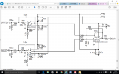
I wish to use a dual opamp in a DAC output circuit that uses two single opamps. The reason being I recently used a MUSES01 in a DAC that uses one dual opamp for both L and R channels and found it is extremely good that I wish to use the same opamp in another DAC board that uses two single opamps. The output circuit does not show the ground pin but there is a ground pin on the PCB in each channel that uses two single opamps. Do I just forget about the ground pin?
I wish to use a dual opamp in a DAC output circuit that uses two single opamps. The reason being I recently used a MUSES01 in a DAC that uses one dual opamp for both L and R channels and found it is extremely good that I wish to use the same opamp in another DAC board that uses two single opamps. The output circuit does not show the ground pin but there is a ground pin on the PCB in each channel that uses two single opamps. Do I just forget about the ground pin?
Attachments
There is no ground pin of an op.amp. It has + and - power supply pins, both referenced externally to GND.
What stops you from using a dual op amp instead of 2 single ones?
It's exactly the same, you'll just have to plot your PCB accordingly.
It's exactly the same, you'll just have to plot your PCB accordingly.
A single opamp package has one opamp fed from one set of supply pins. A dual opamp package has two opamps fed from one set of supply pins. You can combine two single opamps to get two opamps fed from one set of supply pins. You cannot separate a dual opamp package into two single opamps each with their own set of supply pins. As others have said, opamps don't have a ground pin.
So if you need separate supplies you can't do it; you can't separate what is joined within the package. If you are happy with common supplies then there is nothing to do, as the dual opamp already does it.
So if you need separate supplies you can't do it; you can't separate what is joined within the package. If you are happy with common supplies then there is nothing to do, as the dual opamp already does it.
Are you (the OP) talking about using an existing circuit board, or laying our a new one? If the pcb exists, then adapting a dual to fit in the footprint of a single is possible, but probably not available off the shelf. You could make a daughter board style adapter, but the question then becomes "Is it worth it?".
RE re re reading your question, and assuming a couple things which are not clear:
1) I assume you already have that DAC board, it currently uses NJM5534D (0.84U$) and want to use Muses01 (U$45) instead, because of a perceived better quality.
2) want to get/build an adapter board which allows you the replacement, without designing and building a full new DAC PCB
3) not sure it isn't available somewhere, wouldn't be surprised, but you can easily design and reasonably build , depending on your expertise, an adapter board which connects *one* of Muses01 internal Op Amps (pick one) to a male DIP connector matching single Op Amp pinout.
The unused Op amp must be "neutralized" ; standard practice is to short OUT and - IN pins, and tie the +IN pin to some suitable voltage, typically ground.
You will need 1 Muses01 for each NJM5534 substituted, somewhat more expensive but I guess that's not the point, you'll also increase current consumption but I guess that's not the point.
Won't comment on the supposed Audio benefits provided by Muses01 , specially since its own makers decline to do so , just claiming:
It is the best for audio preamplifiers, active filters, and line amplifiers with excellent sound.
Employing the high-purity oxygen free copper of lead-frame which has a greater effect on the sound quality,for the first time in the world*
Pursuing the excellent sound moving person's heart that can not be shown in specification numbers
Hi,
There is nothing stopping you building an adaptor that lets you
use a dual op-amp in parallel instead of a single in a socket.
(You need to add say 22R to each ouput for current sharing.)
rgds, sreten.
There is nothing stopping you building an adaptor that lets you
use a dual op-amp in parallel instead of a single in a socket.
(You need to add say 22R to each ouput for current sharing.)
rgds, sreten.
To clear up my muddy question:
1. I want to use one dual opamp on an existing DAC PCB that uses two single opamps.
2. I don't want to lay a new PCB using one dual opamp instead of two single opamps.
3. The existing DAC PCB that uses two single opamps has a group pin in each channel but a dual opamp does not have ground pin.
My concern is do I just ignore the group pin?
Calling ground "group" doesn't exactly clear things 😉
In any case,
a) existing PCB has a ground "pin"?
Cool, leave it untouched.
You are substituting Op Amps,and neither the old one nor the new ones have ground pins , so I don't see you have a problem.
b) you can't split a dual Op Amp case open and extract one of them, so you'll have to use it as is.
Practical way is to use one and neuter the second one; I suggested one way, Sretten suggests parallelling them , which is an interesting option if application allows it, what you can not do is leave the unused one fully unconnected because it will still share power pins.
3) never comment on subjective parameters for obvious reasons, but in this particular case fail to see what improvement might come from an Audiophile part when applied to such a mundane task as active lowpass filtering or integration, not a delicate task by any means.
Not sure how one Op Amp can "sound" better than another here ... as long as it meets required gain and bandwidth, on which both are overspec'd.
4) back to original DAC improvement: search for a ready made board which allows plugging 1/2 Dual Op Amp into a single DIP8 hole pattern.
In fact, since MUSE01 is available in SMT package (which by the way is cheaper) the resulting adapter board can be quite simple and compact, almost DIP8 package size.
If not, you can make your own; it's a skill worth learning ...... specially here in DIY Audio 😉
For small delicate work I'm a big fan of Photopositive PCBs , incredibly professional looking resulkts with minimum mess.
Much easier and 10 times better looking than second best option: thermal transfer laser film.
Only chemical needed, the etch tank, can be as simple as a wineglass or small Tupper container (given these are thumbnail sized PCBs) and of course a small hand held drill, a Dremel type tool is always useful for countless DIY tasks.
Did I mention that photopositive etch resist acts both as solder resist (protects copper from oxidation) and solder flux (melts with solder temperture leaving bright clean copper behind).
Thanks, muddy clarification for muddy question.
I'll leave the ground pin untouched and share the MUSES01 for the single L and R channels when I return from trip 10 days later.
I'll leave the ground pin untouched and share the MUSES01 for the single L and R channels when I return from trip 10 days later.

- Status
- Not open for further replies.
- Home
- Design & Build
- Parts
- How to use a dual opamp separately as two single opamp