Hello guys,
Please don't kill newbie...
Have a difficult time to understand description of different transformers.
I would like to make a wright choice of transformer for mine project,with is building rack with separate boxed power segment, preamp and 4 stereo amplifiers same thing like this.
From mine power block I would like to have few 12V DC and
4 outlets for amplifiers,those as usual request twin voltage same thing like AC22-0-AC22 ,would be nice 3-4 A current.
Back to transformer:
Toroidal type has clear description:
220 V primaries ( in mine case) and same secondaries like
2x 12 V, I think this means -12V- 0-and +12V
Transformer like this has the same description as above :
2x 12 V witch I think means -12V- 0-and +12V
R-core transformer like this
described like having secondaries like 0-18 V. Does this mean as in reality are -18V -0- (+18V) as well ?
Thank you for advise
Transformer secondary voltages are AC numbers, so no - or +. They are also RMS so to get the peak output voltage (which is what you get when you rectify to DC, unloaded) you need to multiply by sqrt(2).
In practice the AC voltages are those when fully loaded, unloaded you should add the transformer's regulation to get the voltage.
In practice the AC voltages are those when fully loaded, unloaded you should add the transformer's regulation to get the voltage.
described like having secondaries like 0-18 V. Does this mean as in reality are -18V -0- (+18V) as well ?
Notice that two 18V AC secondaries are listed. They are electrically separate, and can be connected in series,
to form a single 18V-0-18V center tapped winding.
Each winding has a phasing dot when shown on a connection diagram, and the "dot" end of one,
connects to the "no dot" end of the other. http://www.hammondmfg.com/5CHook.htm
Last edited:
The Ebay amplifier is specified for a centre tapped 22-0-22Vac transformer.
A dual secondary 0-22, 0-22Vac transformer can be converted to a centre tapped, very easily.
A centre tapped (3 taps on a common winding) cannot be converted to a dual secondary (two separate isolated windings, each with two taps = 4 wires on output).
The transformer maximum Output voltage is:
Mains input voltage / Rated primary voltage * Rated output voltage * 1+transformer regulation
eg 230:22-0-22Vac, 200VA, 7% regulation connected to a 253Vac mains supply will have a maximum output voltage of
254/230*44*(1+0.07) = 51.8Vac
After passing through a bridge rectifier the maximum DC voltage will be ~72Vdc
The two capacitors used to create the dual polarity supply will each see ~36Vdc
You can use 40V, or 50V, polarised electrolytic capacitors.
DO NOT use 35V capacitors.
On a nominal 220Vac mains supply that typically runs at 225Vac during the evening/overnight the typical voltage across the capacitors/amplifier will be 225/230*22*1.03*sqrt(2) -0.7 = ±30.6Vdc (I find that during quiet to medium music reproduction that a regulation/2 factor models the output voltage better than any other model I have seen used)
Last edited:
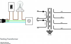
Use a Mains Bulb Tester to check the transformer wiring before connecting the PSU.
Continue to use the Mains Bulb Tester to power ON after EVERY modification.
Continue to use the Mains Bulb Tester to power ON after EVERY modification.
Having got the voltage right, you then need to get the right current rating. Many people think that you can run a 200W amplifier from a 200VA transformer, but it doesn't work like that.
Having got the voltage right, you then need to get the right current rating. Many people think that you can run a 200W amplifier from a 200VA transformer, but it doesn't work like that.
If one has a 160VA transformer and a ClassAB 200W into 8ohms amplifier, then it will manage 20W output continuously without any reliability concerns.Most likely one can if one's interested in playing music through it, rather than test tones.
I was thinking classD when I wrote that - for classAB I think it gets to be a bit marginal what you've stated there Andrew. At 20W output the heatsink is going to be doing about 80W due to the inefficiency of classAB. Into a reservoir capacitor load the power factor's not going to be very close to unity.
The OP hasn't told us, so it could even be Class A (unlikely, I know!). To find VA in from W out you need to know the amplifier Class, the PSU type (probably cap input - but who knows?) and the signal duty factor (which relates to both the amplifier usage and the type of music). If he is listening to real orchestral music in his home then a 200W Class AB amp could probably be run from a 150VA transformer. If he is listening to modern highly processed pop at high volumes then he may need 500VA. If it is a Class A amplifier then 1000VA or 1200VA. These are all per channel, so double for stereo.
Having got the voltage right, you then need to get the right current rating. Many people think that you can run a 200W amplifier from a 200VA
transformer, but it doesn't work like that.
Hi,
No it doesn't strictly follow that sort or reasoning, but in fact it is true.
D.Self has shown that for decent quality music programme on the point
of clipping the actual level is below 20% of maximum 80% of the time.
Pans out transformer VA = power output is about the right minimum,
if your trying to design a cost effective commercial amplifier. For DIY
the marginal costs of a bigger transformer outweighs any scrimping.
Doesn't work for subs and instrument amplifiers though, you want VA
to be at least 150%, 200% is better, of the amplifiers maximum output.
rgds, sreten.
Guys... you are just brilliant thank you fro spending time to teach dummy. I was trained to be designer ,so if you guys have nothing against I will tray to illustrate our post visually. Quite sure as other people having minor knowledge about those things will get same thing from it.
Actually I read a bunch leads on forum (got mine head spinning).
But I will take actual transformer as example,so called R-core. This what I found about those:" R core transformer has high isolation degree. it can improve the signal-to-noise ratio, isolate the harmonic interference, reduce the noise, make he background cleaner. R core transformer can fully improve the quality of sound".
Guys take a look at mine sketches,please comment on mistakes. When we finish correct them I will make nice diagrams.
Attachments
I view this as advertising that exaggerates to gain sales." R core transformer has high isolation degree. it can improve the signal-to-noise ratio, isolate the harmonic interference, reduce the noise, make he background cleaner. R core transformer can fully improve the quality of sound".
In my view most of that is untrue.
What remains is no different from any other CE marked mains isolation transformer.
That Rcore has 4 secondary windings and two primary windings.Guys... you are just brilliant thank you fro spending time to teach dummy. I was trained to be designer ,so if you guys have nothing against I will tray to illustrate our post visually. Quite sure as other people having minor knowledge about those things will get same thing from it.
Actually I read a bunch leads on forum (got mine head spinning).
But I will take actual transformer as example,so called R-core. .............
Guys take a look at mine sketches,please comment on mistakes. When we finish correct them I will make nice diagrams.
One side is phase marked to look like the other side. On the R cores I got from Selectronic, the phase marking, by colour codes on the wires is completely misleading. You end up with a shorted secondary and out of phase primary (no magnetic field = enormous primary current = burnt out primary !!!!!!!
Use a Mains Bulb Tester to prove you have firstly wired the primary correctly and then wired the secondary correctly. Do wire primary first and TEST your wiring.
Last edited:
You don't need the OFF/ON switch, it's a nice to have option.
I screw an insulated terminal block to each individual tapping. This insulates all the primary and all the secondary wires from accidental contact. Just me playing safer.
The Yel to Grn will either be right, or wrong.
The bulb will light up if it is wrong and reduce the input voltage to <5Vac. Equals no damage.
If the winding colours are correct, then the bulb will not light up. It might not even flash.
The full mains voltage will be at the input. Be careful.
Unplug.
Now start on the secondary connections.
Find which tappings are on the SAME winding. Label them A & B
Connect one A tap to one B tap.
Power ON via Mains Bulb Tester. Because two tappings are open the bulb should not light. If you accidentally connected A to A and/or B to B then the bulb would light.
Measure the voltage across the two AA tappings.
Measure the voltage across the two BB tappings.
Measure the voltage across the open A & B tappings.
Power OFF.
Last edited:
Now start on the secondary connections.
Find which tappings are on the SAME winding. Label them A & B...
I hope you know this is ambiguous. More than 2 taps (4x2 actually) and only 2 letters, without a correct command how to match them. I think it is understandable only for those who already know how to connect a transformer. And actually in this case labelling this way is not neccessary at all, since they are color coded.
Gin8330!
There are 4 secondaries printed on the label, and more than 4 wires can be seen on that side, I dont know why did you have to delete 4 taps...
There are 4 secondaries printed on the label, and more than 4 wires can be seen on that side, I dont know why did you have to delete 4 taps...
The lead outs are colour coded. but I have the same transformer and on my transformer there is no labelling to tell the builder which taps are on which winding.I hope you know this is ambiguous. More than 2 taps (4x2 actually) and only 2 letters, without a correct command how to match them. I think it is understandable only for those who already know how to connect a transformer. And actually in this case labelling this way is not neccessary at all, since they are color coded.
That's why I said that the Builder should label the winding as either A, or B.
Each limb has two winding = 4 taps. That needs just two winding letters. A & B would do, or use JK, or XY.
There are only two secondary windings. The other two secondary winding are on the OTHER limb and cnnot be confused with the first two.
But there is an issue with identifying the correct phase.
That's why I siad the Builder should use a Mains Bulb tester.
Last edited:
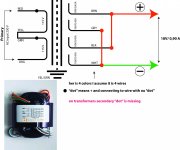
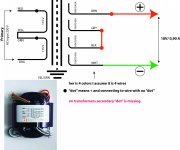
OK guys..have make a drawing Step 1.
Know is a question witch wire where to connect ans what purpose of test it would be?
You are still showing 4 wires for the secondary, but there are 8 wires.
Brn1, Brn2, Gry1, Gry2, ...
You have 18V between Brn1 and Brn2. Also 18V between Gry1 and Gry2. Also ...
To get more Amp from the secondary but still 18V, you have to paralel the wires.
So connect Brn1, Gry1, ... All 4 and also connect Brn2, Gry2 ... Ending up with 18V with 1,8A. But that is not what you want.
If I understand, you want -18-0-+18V with 0,9A.
So you need 2x 18V 0,9A secondaries.
You connect the first 2 secondaries Brn1+Gry1 and also connect the Brn2+Gry2. Now you paralleled the Brn and Gry lines.
This line is now the first 18V 0,9A secondary.
Second is the Blk1+Wht1 and the Blk2+Wht2.
Now to get the 0 point you connect the Brn2+Gry2 and the Blk1+Wht1.
So the -18 is the Brn1+Gry1
The 0 is Brn2+Gry2+Blk1+Wht1
And the +18 is Blk2+Wht2.
The problem is to know which line is 1 and 2 at all the colors.
Because if you connect Brn1+Gry2 and Brn2+Bry1 then you will force the secondaries to work against each other.
This is what AndrewT is trying to describe. That is what the dot is for.
Hope I'm understanding the problem.
Last edited:
- Status
- Not open for further replies.
- Home
- Amplifiers
- Power Supplies
- How to understand description of different transformers