Hi there,
I purchased a few large (100000uF, 30V) Sprague caps a while back. They were a clearance item so I have no idea of age at all, and I was wondering if there's a way to test them at all? I have 8 of em, and due to size I can only use 2 of them in my current project (an F6), so if there's a way to get the check through and select the best of them, that'd be handy.
Any suggestions?
I've tested large caps like those on my LCR meter. The capacitance range on mine only goes up to 10,000uF so I use the impedance measurement function and back-calculate the capacitance from the measurement of the capacitive reactance. For example 100mF should have 32mohm at 50Hz.
Its also worth testing the leakage current at full rated voltage - do this either with a bench power supply you can set for a low current limit (say 30mA) or with a series R of 1k and a voltage source.
Its also worth testing the leakage current at full rated voltage - do this either with a bench power supply you can set for a low current limit (say 30mA) or with a series R of 1k and a voltage source.
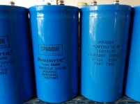
if you can post pictures of the lable we can tell age..
if you have a capacitance meter, that is one way to do it...
reforming those caps before testing is also a good way to start...
http://www.diyaudio.com/forums/tubes-valves/218094-elecrolytic-capacitor-reforming.html
Reforming Electrolytic Capacitors
if you have a capacitance meter, that is one way to do it...
reforming those caps before testing is also a good way to start...
http://www.diyaudio.com/forums/tubes-valves/218094-elecrolytic-capacitor-reforming.html
Reforming Electrolytic Capacitors
I reform much slower and for much longer.
I do know this results in very low leakage after being reformed.
What I don't know is whether the slow reforming leads to a longer life before reforming is needed again.
Why does reforming need to be done again?
Because the excess voltage tolerance above the operating maximum voltage gradually drops away.
A 50V capacitor reformed to 50V, but used in a circuit that never exposes it to more than 3V, will gradually un-form itself down to a 3V capacitor.
You can reform them all at the same time.
Attach a >10k resistor to each +terminal.
Join all the free ends together. Apply +ve to the new 8way junction.
Join all the -terminals together.
Apply -ve to the new 8way junction.
The voltage drop across the resistors show which caps need more or longer reforming.
Expect a 1:1.2 ratio of worst to best.
I have found that 24hrs reform, then 1minute discharge, rest for 24hrs, then another 24hrs slow reform, gives much better results than keeping the caps up at full voltage for 48hrs.
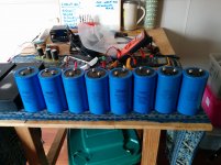
Done - photo's attached.
I'll get reading that reforming process - thanks for the tip!
i could be wrong, but year seems to be 1987 workweek 13 in one
and the other 1985 workweek 21,
those are the numbers that makes sense for dates...
a 50 volt supply at least and 10k 5 watt resistors each can,
soak test until leak goes to less than 1mA,
never mind if the cap voltage goes above 30 volts, as long as leakage
is below 1ma, then you are fine..
make sure the rubber seals are intact and the cap never vented..
install a jumper between terminals after discharging the caps to prevent DA....
keep the jumpers on until ready to install in circuit...
Thanks!
Done - I've a bank of 6 caps on my desk currently forming. R = 23K on each. I'll leave them here overnight and and have a look again in the morning and see where they're at. They all see to look ok, but I recall when I got them I rejected 2 as having a rattle/loose sound internally, so who knows what sort of life they've had?
Anyway, thanks for the help! I've bought quite a few clearance caps from the same source - should I assume that they could all benefit from similar treatment? I'll probably go ahead with it anyway - It can't hurt surely?
Cheers,
Aren.
your call, but i do not see any need to test overnight,
as soon as you get leakages not more than 1mA or thereabouts,
then you are good to go..
you may also see how low leakage can get..that is where you need more time,
but no big deal really...
as soon as you get leakages not more than 1mA or thereabouts,
then you are good to go..
you may also see how low leakage can get..that is where you need more time,
but no big deal really...
more caps
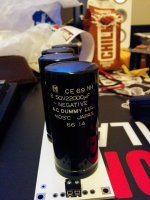
...Actually, would that make these caps likely to be 1966 vintage?
I bought these a little while back and mounted them recently on one of TeaBags PSU PCB's with a view to using them in an F3 build I've been planning for a while.
I guess they'll need to come out of the PCB if I'm to revive them which will prove tricky given they're four lug caps.
...Actually, would that make these caps likely to be 1966 vintage?
I bought these a little while back and mounted them recently on one of TeaBags PSU PCB's with a view to using them in an F3 build I've been planning for a while.
I guess they'll need to come out of the PCB if I'm to revive them
which will prove tricky given they're four lug caps.Attachments
Oh, and thanks for the comment about testing overnight - I probably still will as I'm off for dinner just now, and unlikely to be too concerned when I get back 😀
...Actually, would that make these caps likely to be 1966 vintage?
I bought these a little while back and mounted them recently on one of TeaBags PSU PCB's with a view to using them in an F3 build I've been planning for a while.
I guess they'll need to come out of the PCB if I'm to revive them
not sure now how the japs datecode their caps..
if leakage is good and caps measure right,
then nothing to worry about..
oh, i will never leave a test set-up unattended, but that is just me...😉
I see you are discussing here about measuring large capacitors.
I made some measurements with an impedance anallyser on different capacitors, not realy verry big but...
The bigest capacitor tested was ELNA for Audio 15000µ/63V.
All capacitors starting 2200µ (verry good ones - automotive with only 14mΩ ESR) and until ELNA for Audio (15000µ/63V) show resonance under 20KHz.
The Elna resonate at 7KHz and over 9KHz presented inductive behavior.
Question: how can a capacitor like this to ensure higher frequency audio band filtering. Putting in parallel polyester (WIMA) and/or ceramic capacitor between 0.1μF and 20μF not helped significantly.
localized filtering using smaller valued caps should help right at the amp board and close to the output transistors....
There's a great thread a while back that was fascinating for how far they pushed the idea of inductance and resonance in caps. Hang on I'll try and find it...
http://www.diyaudio.com/forums/powe...evoir-capacitors-chip-amps-3.html#post3608500
was the logical extreme reached. 🙂
Having left the caps for a few hours, the spread of voltages over the resistors on the caps is about 600mV - 200mV. I'll leave it over night after I nudge the voltage up to the rating.
And all good. The best of them had about .15V across the 28K resistor feeding the +ve terminal, so I make that to be roughly not very much in terms of leakage current. So all good there; thank you for the assistance!
Voltage across the cap? It would have been ~29.5V generally across the group.
Have I misunderstood the process? As I measured it I had way less than 1 mA flowing into the cap, hence the leakage must equal that amount. Or have I misconstrued?
Have I misunderstood the process? As I measured it I had way less than 1 mA flowing into the cap, hence the leakage must equal that amount. Or have I misconstrued?
- Status
- Not open for further replies.
- Home
- Amplifiers
- Pass Labs
- How to test large capacitors?