wanna see, the tda7052 is a quite decent chip i just have to say 😀
make sure the volume pot has a voltage divider before it.
thing is, full blast volume is reached after -if i remember correctly- something like 1.4 volts or so.
over that volume does not increase, but it has some goofy effect on the distortsion.
i gona wait for the schematic, i might have a solution to have the thing working in btl with the 8 ohm speaker, and otherwise work in SE.
actually i'm planning to get a handfull of these chips, for a multichannel volume controll.
the thing is i failed to find anything that would do the trick, and i figured this might cut it.
needs it for a 5.1 amp. dunno how well will it play out 😀 only thing this chip is missing is external gain setting resistors, and the ability to work with a gain of 1.
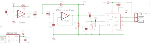
Ok lets see if I can get this to upload an image of my schematic. I want to be clear, there is no problem with running this thing in BTL or SE modes. It will fill a room with clean sound on a 9V battery.
The problem I have lies in the fact that a bridge tied load uses both terminals of a speaker. (It has to do this because the signal is floating at half VDD). In my case this removes any access to the common ground that a microphone PTT needs to activate.
Connector K7 leads to a 3 terminal jack where the speaker mic plugs in. On previous versions I used a LM386 amplifier where the 7052 is now. In that configuration the speaker uses common ground and the PTT functions fine. This whole exercise is an example of project creep at this point.
I tried this to see if I could get the circuit to work in BTL mode and somehow find a way to provide a ground path for the microphone to function. I don't have the microphone circuitry unfortunately. In any event I believe the answer lies in the mic. I need a mic circuit that allows the speaker to operate as a bridge tied load while providing a ground path for the PTT.
 Schematic replaced as requested.
The problem I have lies in the fact that a bridge tied load uses both terminals of a speaker. (It has to do this because the signal is floating at half VDD). In my case this removes any access to the common ground that a microphone PTT needs to activate.
Connector K7 leads to a 3 terminal jack where the speaker mic plugs in. On previous versions I used a LM386 amplifier where the 7052 is now. In that configuration the speaker uses common ground and the PTT functions fine. This whole exercise is an example of project creep at this point.
I tried this to see if I could get the circuit to work in BTL mode and somehow find a way to provide a ground path for the microphone to function. I don't have the microphone circuitry unfortunately. In any event I believe the answer lies in the mic. I need a mic circuit that allows the speaker to operate as a bridge tied load while providing a ground path for the PTT.
Schematic replaced as requested.Attachments
Last edited:
ah, i see now.
hmm interesting problem.
a not so obvious solution would be a transformator , lol.
1:1 ratio, ~8 ohm on the side where the 7052 would connect.
on the other side you can then have a ground references output just like if it was single ended all the way (i think)
question if it would worth it at all.
i'm not familiar how the push-to-talk stuff is achieved.
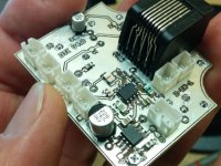
The transformer idea might actually work but it's impractical considering the size of the board. Shown is the top layer and as you can see it's not much larger than a 9V battery. The 7052 is in the lower left corner with K7 to the right. I think I'll try to find a 2 plug mic and see how that works out. I'll post it here just for interest. Otherwise it's back to the old 386 and this board delivers music in my shop.
Attachments
How about tying a 100ohm resistor between the+ and- outputs to satisfy the chip and then the 8 ohm speaker and a cap in series with the speaker to ground and + output.
How about tying a 100ohm resistor between the+ and- outputs to satisfy the chip and then the 8 ohm speaker and a cap in series with the speaker to ground and + output.
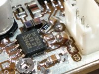
Interesting idea however after thinking about it I don't believe that's any different than single ending the chip the way I did it earlier with a cap in series off the the positive output and a 50 ohm resistor and cap in series to ground off the negative output. Added a pic to show that on-board adaption. The 100 ohm resistor would sit at half the supply and prevent the speaker from seeing anything other than the positive output which is only going to be a few mW of output. Again it's not enough to drive the speaker.
I'm sitting here right now with crystal clear Dire Straits's, Telegraph Road filling my lab on a 9V battery and really wanting this quality of sound in the radio mixer. I'll give this suggestion a try just because and let you know.
Attachments
Yes it would definitely drive a ouple of power transistors but I'd go back to the LM386 before I did that (thanks anyway for your input). The TDA7052 is designed to work bridged and it does it well so I'm keeping it in there if I can. Single ended using one output is fine for an earbud or mono headset but that's it. I'm talking to a manufacturer about a speaker mic wired to work the way I want with positive and negative speaker, mic and ground pins on a single plug.
I was thinking BCP56 (similar to nos gray philips drivers).
2SD667, BC639, BC327 are other examples of the "Mini Drivers" category.
Alternatively, an op-amp configured as an "instrument amp" balanced drive input, can use your bridged output. The added op-amp can then push the speaker single-endedly.
2SD667, BC639, BC327 are other examples of the "Mini Drivers" category.
Alternatively, an op-amp configured as an "instrument amp" balanced drive input, can use your bridged output. The added op-amp can then push the speaker single-endedly.
Hmm, interesting suggestion thanks. Not sure if adding yet another stage is the way to go but it's worth checking out.
Looking at those drivers now. Are you suggesting a push pull section driven by a single 7052 output? Version 1.0 of this device used a push pull final section and I immediately moved to the LM386 in ver 2 to reduce distortion effects at higher volumes.
With the transistors, I had something in mind for sure; however, I wouldn't have the skill for it, so I'd personally have to use an op-amp.
As suspected the solution was to get a speaker microphone wired for a bridged load.
One thing I did notice though was the heat. Had it running a fairly large speaker in my shop for a day which probably drew the full output capability of the chip. Could still hold a finger to it but I was suprised at how much heat it was producing. Since this is a communications system with a modest duty cycle it won't be a problem but for heavy duty applications like music it would be a consideration. Whats out there for heat sinking on SOIC pakages and the like? Other then sufficient copper pour to wick off the heat what options do you have? I don't do much in the way of audio circuitry so heat sinking is rarely an issue for me.
One thing I did notice though was the heat. Had it running a fairly large speaker in my shop for a day which probably drew the full output capability of the chip. Could still hold a finger to it but I was suprised at how much heat it was producing. Since this is a communications system with a modest duty cycle it won't be a problem but for heavy duty applications like music it would be a consideration. Whats out there for heat sinking on SOIC pakages and the like? Other then sufficient copper pour to wick off the heat what options do you have? I don't do much in the way of audio circuitry so heat sinking is rarely an issue for me.
Thermal adhesive (applied carefully so that it doesn't smoosh out onto the pins), can stick a little heatsink, like the Mini 2CHANNELS TPA3123 Class D Digital Amplifier Board Assembled 20W 20W | eBay TPA3123, ebay#321232086753 Have a look at the heatsink on that listing's photograph.
Alternative: Computer motherboards hold a heatsink on with a metal spring to keep it in place, and with that approach, ordinary white thermal paste is used. Arctic Ceramique is non-conductive and may be used.
Alternative: Fairly thick traces can be used, and they can be left uncoated, so that they may be fluxed and solder added to the traces to further thicken them. This will efficiently draw heat out of the pins. Its very easy with PDIP, but not so blissful with SOIC.
Assured stability is an additional way to run the audio amp a little bit cooler.
Really good decoupling (such as nearby 47u~220u) caps next to the chip, will probably run cooler than ringingly large 1000u and larger caps (no problem, large caps may be used after installing the smaller caps).
And, how are you set for cool air intake vent (under) along with hot air output vent (above), for convection airflow path to remove heat?
An emitter resistor could cool it off, but at some cost to output power. The linearity may improve with that approach though (depends on the needs of the speaker). Some frequency contouring is also possible, with an emitter resistor paralleled with a small value cap, such as 0.68u.
When it comes right down to it, best results may necessitate a more efficient speaker with a lighter load. A 100db efficient 16 ohm or 20 ohm speaker may be suitable (and scarce). That kind of speaker was commonplace from the late 50's through the early 70's. Today, you'd be looking at an MTM or WWT, involving a pair of Very high efficiency 8 ohm speakers in series to make a 16 ohm load. That will cool off your amp but also thin your wallet.
You could cheat a little with the audio coupling if you know your target speaker bass frequency response capacity. This idea is useless for a 15" speaker but may be even vital for a 4" speaker. Reduce the size of the input coupler cap (application may also depend on source output), the negative input coupler cap (its probably already too small, so there's no need to change that one) and the speaker output cap (give it one if you don't have one). . . until the caps are just barely big enough so they don't interfere with bass response from the speaker. If installing an output cap on an amp that doesn't require it, put the cap on the speaker negative.
Set the input cap and output cap to match speaker low frequency capacity.
After that mod, signal below speaker capacity doesn't pointlessly overwork either the amp or speaker (so at least what little amp power you have, doesn't get wasted).
Bonus: The end result (for a small speaker) is a higher capacity and higher fidelity during loud playback.
This looks weird in print, but it is actually very similar to bi-amp, except that instead of a mids&treble amp with a separate woofer amp, you're doing just one midbass&mids&treble amp (with the filtering not really different except bigger and there's no sub amp used).
My handmade table radios use that filtering to avoid clipping and reduce speaker distortion.
Full range speaker distortion of the treble happens because the cone movement modulates the treble, effectively breaking it up, and while cone movement to output useful bass is acceptable, cone movement for attempted output below speaker capacity, with the cone shaking for pitches gone unheard, is not acceptable and incurring speaker distortion is not a good use of amplifier capacity. Simple filtering fixes both.
Woofers up to approximately 8" can use this filtering.
So, that was, increase surface area, check the stability, refine the decoupling, increase ventilation and lighten the load.
P.S.
An alternative option (buffer) is to purchase an amp that needs a differential input and then have the little SOIC part drive that power amp (the awfully funny thing about that suggestion is that probably a lot of people on the chip amp and discrete amp forums are searching for the good sounding bridge adapter amp, and your little SOIC could do that job easily). Little parts like that are well suited to the smaller job of "driver" so that plan does make some sense.
The option of driving a power amp with the little SOIC headphone amp, is viable for almost any speaker, even if the speaker has a series crossover.
P.P.S.
A different alternative (Bi-Amp) is to use the little SOIC as a delightful "mids&treble" amplifier (padding/emitter resistor gets the load down to 12R or lighter so easily) and then add a woofer driven by its own amp. That latter idea doesn't lack for power and could possibly increase fidelity dramatically. Voltage headroom: Tubes do just about what you'd expect, but solid state needs about 6 times the power for "headroom" to preserve fidelity (because apparently tube clippy muck sounds okay, but transistor clippy muck sounds just awful). Current headroom: All amplifiers share the concept of linearity, which if you run the outputs past the optimal capacity (a miniscule fraction of the published headline capacity), you no longer have a concert sound but instead the speakers draw attention to themselves and sound a bit fake or a tonal errata or blare.
Heat on a part that small means that maximum quality is NOT available, because linearity is shot (insufficient current headroom).
Parallel amp is one possible solution, and Bi-Amp is another. For your system, where you really want to enjoy the output of the little SOIC part, I suggest Bi-Amp, with it driving midrange and treble speakers, and some beater amp driving the bass to a woofer. Thus the linearity of the little SOIC is preserved so it can operate at maximum quality. Also, no heat, and it probably wouldn't ever wear out.
This option can work for a speaker that has an ordinary parallel crossover--see rewire for bi-amp.
Last edited:
A comprehensive answer full of good info. Unfortunately most of it cannot be applied here.
This audio system is in a small waterproof box so no ventilation at all. All components were selected for their temperature range for that reason. To make matters worse its going to be strapped to a tactical vest in 30 degree heat and pounded into the dirt so anything likely to come loose like a spring or even a conductive adhesive is a poor candidate. I have no idea what the enclosure temperature will get to.
Frequency shaping the output isn't really an option either I would think since it's all filtered though a 3KHz low pass ahead of the chip amp anyway .
Input coupling is done at every stage using .47uF metallized acrylic film caps. The BTL output should not be coupled. Supply decoupling for the 7052 is done with 220uF electrolytic however I'm not sure it's doing much with the regulated supply. All mixing and filtering are done with Panasonic ECPU-A series caps and .1% thin film resistors to assist in stability and reduce noise, both positive and negative supplies are regulated and every chip on the board except for one logic inverter is decoupled.
I have no (or very little) ability to control the speaker selection since I'm restricted to available (and suitable) speaker microphones which is generally 8 ohms.
I could look at output resistors but the entire board is about the size of a 9 volt battery so space is very limited as it is and heat in the chip or in the resistor still has to be dealt with. I could go to an all metal box and try to use that for cooling somehow but weight is also a consideration and previous versions used tough ABS enclosures without a failure. Adding significant weight just for cooling one chip is not going to be well received.
In normal use the circuit will see voice frequencies only and the speaker will be bypassed with an ear piece. If an open speaker is used at all it's at middle volumes. The only reason I noticed the heat is because I was piping music through it from my phone to a big speaker for fun. Not a likely field scenario but it got me looking for SOIC heat sink options, I don't see a lot. Originally this was a single ended design and heat issues never arose. The only reason it's now a bridged load is for better sound on the occasional time the speaker is used. In fact I now have to contend with the additional power since all volumes need to be turned very low to be comfortable. Accidentally turning the volume down has happened in the past by rolling around on the control module attached to the front of a vest. That would be even easier to do if the volume was already low. I'm actually considering reducing the mixer stage gain to compensate and adding a lockout to the volume buttons.
I really wanted to leave copper pour under the chip in the initial board design but the area was needed for tracks. If heat did turn out to have an effect I would try beefing up the pin tracks like you mentioned and experimenting with adhesive sinks (I have this scary vision of a heat sink rattling around in there at the worst possible moment).
Before you ask, no this is not a military application. It's for crazy serious airsoft and paintball players like myself and the guys on my team. I invented this gizmo a few years back so we could use multiple radios. Everything, radios and all, are carried on the back. A control module (the size of a 9 volt) is used for volume and transmitter selection. This stuff really takes a beating so it has to be made as tough as possible.
Good ideas for discussion though so thanks.
Last edited:
if you could mod the small waterprrof box, then you could actualy use that as a heat spredder.
how far is the chip from hitting the wall of the box?
prehaps all you need is to make a cut, glue a piece of aluminium on from the outside with a good glue, to keep it waterproof.
then , if the gap is not too large, you can use thermal pads to make the chip contact the newly made heat spredder.
if the gap is too large for that, you might need some wizzardy done to the aluminium sheet. i see no reason why it could not be done.
maybe you gona have to make the aluminium shaped into a Z form,
the top of the Z glued onto the box, the mid part would sortha act like a spring, and push the bottom of the Z form against the chip. then the thin self-adhesive thermal pad (sticker style) can do the rest of the work.
shock resistant for sure, still maintains serviceability if needed, and will keep the lil bugger cold.
We're on the same page. While writing the last response I realized that all the chips on the other side of the board actually contact the enclosure (like I said, space is minimal). If it became necessary I could relocate the 7052 to the other side and glue a thin sheet of heat sink to the enclosure wall.
Just reduced the mixer gain by 10 to allow more headroom on volume control which worked out well. The 7052 only had to draw a mA more if that. No I think I'm going to go without a sink on it if for no other reason than a test of its capabilities in this application.
As an aside, I just ran an operating cell phone and a transmitting FRS radio around the bare board. The only thing I got as RFI was a slight hum from the radio and a few soft HF clicks from the phone if they were held right up to it. I'm very pleased with the filtering. I could probably get rid of this crap too if I used SMD feed through capacitors on the input. I'd love to try that out. It seems like all of it is getting in via the RJ45 connector which is not shielded because I couldn't get one shielded in the form I wanted.
So...the end result of all this is;
Yes the 7052 can be single ended by capacitively coupling the positive output to the speaker and using a resistor and cap in series on the negative output. The output is enough to drive a mono ear-phone but thats it unless you add another stage.
If you were using it with a 2-way or 3-way speaker for "test" then it was already run coupled when driving tweeter and or midrange and tweeter (your crossover has a series cap). So, using it coupled to drive a very small speaker is not a different concept. And, very much like a midrange or tweeter, any little speaker can play louder and clearer when coupled.The BTL output should not be coupled.
The deal is,
Below the cap crossover frequency, the roll-off acts like a resistor, thus lightening the load. The lighter load will also reduce battery consumption. For use when one had not intended to make a battery powered heater.
One (of several) costs of bridging is that you've exchanged an 8 ohm load for a Pair of 4 ohm loads. Since the enclosure and other design parameters are sealed, I think its time to cheat.
Charge-up of an output cap can be prevented with a paralleled resistor, which is typical for use when the cap is only used for filtering off sub-audible frequencies. In such usage, when the cap is not used for blocking dc, the output cap goes at speaker negative, as close to the speaker as possible.
If that was analog, trimming the pot range would be easy, since lifting the pot ground so it can't go to zilch would make it impossible to turn down too low (assuming that disabling the device was not an intended function of the volume control). Anyway, for bridged you got 6x more gain, so you could alter the input mixer to recoup.Accidentally turning the volume down has happened in the past by rolling around on the control module attached to the front of a vest. That would be even easier to do if the volume was already low. I'm actually considering reducing the mixer stage gain to compensate and adding a lockout to the volume buttons.
- Status
- Not open for further replies.
- Home
- Amplifiers
- Chip Amps
- How to single end the TDA7052