I instaled new power transistors in my ka-5500 and they are very hot after few seconds. How to set them?
please help
please help
I instaled new power transistors in my ka-5500 and they are very hot after few seconds. How to set them?
please help
please help
Jan has already responded, asking the question again and ignoring his useful advice is not going to get you very far.
And are you sure that:
1) Power transistors were the only part that needs change?
2) That the BIAS was set to the lowest position prior to installing new transistors?
1) Power transistors were the only part that needs change?
2) That the BIAS was set to the lowest position prior to installing new transistors?
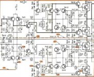
Sorry I thout, that I wrote this post in wrong place and I write it again in other place. Probebly moderator changed this and paste it here. This schema is to big i added onely a piece of it. There are variable resistors (BIAS) but i don't know what voltage on which element should be. Power transistors are 23, 24, 25, 26.
BIAS are not on the lowest position.
sorry Jan
thanks for help
BIAS are not on the lowest position.
sorry Jan
thanks for help
Attachments
You need to turn the bias pot so that the voltage across the output device emitter resistors is as low as you can get. This will mean setting the pot to lowest resistance.
Then increase the pot a bit at a time. You need to aim for about 25-33mV across the output device emitter resistors.
Then increase the pot a bit at a time. You need to aim for about 25-33mV across the output device emitter resistors.
richie00boy said:You need to turn the bias pot so that the voltage across the output device emitter resistors is as low as you can get. This will mean setting the pot to lowest resistance.
Then increase the pot a bit at a time. You need to aim for about 25-33mV across the output device emitter resistors.
Hi richie00boy
Everything you wrote is correct , except that for minimum current across the output devices , the pot must be set at is highest resistance value.
But even if I set the pot on the highest resistance (950Ohm) the voltage on the resistor 27 or in the second chanel resistor 28 (on schema) is about 449mV and it is the lowest I can get.
If you measure voltage across a resistor it means a current is running through that resistor.
In your case, a current through the said resistors is also the current through the output transistors (Q23..Q26)
The amount of current determines that heat dissipated in the transistors. The more, the hotter.
Measure the voltage across the said resistors and calculate the current with I=U/R
I=current
U=voltage
R=resistor
/Hugo
I know that🙂 It is about 53mA. But everything will be all right if this current will be lower (the voltage will be about 20mV)??
Apply a dummy load and no input signal.
With 20mV the current is 42mA, a bit high, aim for 10mV.
What were the original transistors and what did you replace them with?
Is there no indication on the schematic or manual of how much the bias current should be?
Do you measure DC voltage at the output?
/Hugo
With 20mV the current is 42mA, a bit high, aim for 10mV.
What were the original transistors and what did you replace them with?
Is there no indication on the schematic or manual of how much the bias current should be?
Do you measure DC voltage at the output?
/Hugo
- Status
- Not open for further replies.
- Home
- Amplifiers
- Solid State
- How to set Power transistors on Kenwood ka-5500?