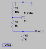
Well, I want to use the tl431 to regulate + and - 12V suplies, and since it's a shunt reg I know it's possible to regulate the negative rail as well, but my question is, how exactly? In a text book circuit for this reg, I'd have a resistor on the rail and then a voltage divider feeding into the TL431, correct? The output voltage behing (1+R1/R2)Vref R1 and R2 being the top and bottom (connected to rail and connected to ground) resistors in the voltage divider respectively, correct? So in a negative reg I'd use a resistor on the negative rail, then again a voltage divider feeding into the TL431, that I know. But if I want the output voltage to be -(1+R1/R2)Vref, then must R1 be the resistor connected to the negative rail or the resistor connected to ground (and R2, obviously being the other one)? I'm gathering that the R1 would be connected to the negative rail, for this would simply result in the same circuit as the positive reg, except with a negative rail and the TL431 flipped, which, would work, right?
Thanks for any replies, I'm just not too sure about this, I would try it myself, but the TL431s haven't shown up (ups ain't that fast) and this is bothering me, I'd like to know.
Thanks for any replies, I'm just not too sure about this, I would try it myself, but the TL431s haven't shown up (ups ain't that fast) and this is bothering me, I'd like to know.
Ah, thanks, I guess I can start work on the pcb layout now 🙂, just gotta wait for the TL431s, that's all that's missing for this project.
Thanks again, but on another topic, I see you used LtSpice to make the schematic, how did you add the TL431 macromodel? I can't seem to figure out how to add models except for the BJT or fet or whatnot models...
Thanks again, but on another topic, I see you used LtSpice to make the schematic, how did you add the TL431 macromodel? I can't seem to figure out how to add models except for the BJT or fet or whatnot models...
I got this model from the files section of the LTSpice Yahoo users group. I tried using the TI model but had all kinds of convergence problems with it. To join the group you need a Yahoo email address. Sign up with the "no email" option (it's really a mailing list archive), then you can browse it like a normal discussion group.
There's a .asy symbol file that I put into a directory I created under LTSpice\lib\sym called "Extras". When I do an F2 to add a component, this added "Extras" folder will appear. Browse to it and select the TL431A. There's a matching .asc file that must be in the same folder as your project. It will be picked up automatically. See the instructions that come with the file for more info.
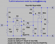
Here's the model. The author, a guy named analogspiceman, looks like he spent quite a bit of time coming up with this. You can see that it models the AC characteristics. I've had zero convergence problems with this model. The Yahoo users group is located at http://groups.yahoo.com/group/LTspice/
There's a .asy symbol file that I put into a directory I created under LTSpice\lib\sym called "Extras". When I do an F2 to add a component, this added "Extras" folder will appear. Browse to it and select the TL431A. There's a matching .asc file that must be in the same folder as your project. It will be picked up automatically. See the instructions that come with the file for more info.
Here's the model. The author, a guy named analogspiceman, looks like he spent quite a bit of time coming up with this. You can see that it models the AC characteristics. I've had zero convergence problems with this model. The Yahoo users group is located at http://groups.yahoo.com/group/LTspice/
Attachments
Quick question, how would one go about calculating the value of the resistor that's on the rail before the reg?
Well, start by choosing R1 and R2 (per the attachment above). The current through the resistor string R1-R2 is Vref / R2 where Vref is 2.5 Volts. So maybe choose R2 = 2.49k to give 1 mA. Then pick R1 to get the desired voltage. You want maybe 1 mA or more through the TL431, so that would be 2 mA total in the absence of a load.
So pick R3 = (Vunreg - Vreg) / Itotal
Where Itotal = current through R1 and R2 (1 mA if R2 is 2.49k) plus current through TL431 (say 1 mA or more) plus the current drawn by the load (which should be low in a good design, otherwise you may need to rethink the design).
So pick R3 = (Vunreg - Vreg) / Itotal
Where Itotal = current through R1 and R2 (1 mA if R2 is 2.49k) plus current through TL431 (say 1 mA or more) plus the current drawn by the load (which should be low in a good design, otherwise you may need to rethink the design).
Ah, I see how it works now, didn't quite understand how the shunt reg would work until your post made me think... and then I got it...
But, how much power can this little to-92 sucker take? Since my load won't be constant, I just want to know at my voltage, how much current can I put through it? Ill be using it lower than the rated 100mA, that's for sure.
But, how much power can this little to-92 sucker take? Since my load won't be constant, I just want to know at my voltage, how much current can I put through it? Ill be using it lower than the rated 100mA, that's for sure.
To determine the maximum current, you'll need to calculate the junction temperature. To do that, calculate the power dissipated as the product of the voltage across it times the current through it. In the TI data sheet, look at the thermal resistance theta_JA, which is 140 deg C per Watt for the TO-92 package. Multiplying this number by the power dissipation in Watts gives you the junction temperature rise above ambient in degrees C (the units cancel). Assume ambient temperature of 25 deg C. So power dissipation in Watts times thermal resistance in deg C per Watt plus 25 deg C gives you junction temperature. Notice frum the absolute max specs that device destruction occurs at a junction temperature of 150 deg C, or 125 deg C rise above ambient. Maybe try to keep the junction temperature down below, say, 70 deg C for maximum reliability.
Oh, just one more thing. If your load current varies a lot, you should consider using a series regulator like the LM337 instead. The TL431 is great for replacing low-power zener diodes, but your load current might spike to a high value and cause the TL431 to turn off. You haven't said what your application is, so it's hard to say.
Just regulating the voltage feeding a low power opamp. Never toyed with the TL431, and I thought now would be a good time to try it out.
I don't think that the current draw will spike enough to affect the TL431 (should be rather low) so I hope I'll be fine. Otherwise I can always revert to a series reg, just wanted to try a shunt this time around though 🙂.
Oh, and again, thanks alot for all your help, I'm almost done my board and I'll see how it works soon enough.
Hi,
I think there was a series of tests on TNT audio with series and shunt regs. In these types of low current apps the shung regs outperformed the series regs, they genrated less noise. So for low current opamps these regs are probably a good bet.
Thanks
Raja
I think there was a series of tests on TNT audio with series and shunt regs. In these types of low current apps the shung regs outperformed the series regs, they genrated less noise. So for low current opamps these regs are probably a good bet.
Thanks
Raja
You can always use the TL431 to drive the base of a PNP or NPN power transistor. Then you don't have to worry (as much)about frying the critter.
Ambient isn't always "ambient" -- as in the case where you put the device in a box with other devices which are heating.
Ambient isn't always "ambient" -- as in the case where you put the device in a box with other devices which are heating.
- Status
- Not open for further replies.
- Home
- Amplifiers
- Solid State
- How to regulate a negative rail with TL431?