I've designed and tested an attenuator based on a multiplying DAC and an opamp. It works really well but I'd like to know if there is any changes I could make in order to improve performance, mainly noise and dynamic range.
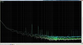
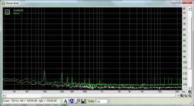
Using my E-MU 0404 for measurements, I think THD is below what I can measure but see the attached RMAA graphs for noise and dynamic range. I have three items on the graphs:
- Loop back = WHITE
- Attenuator with no gain (R2 and R3 removed) = GREEN
- Attenuator with 12dB gain = LIGHT BLUE
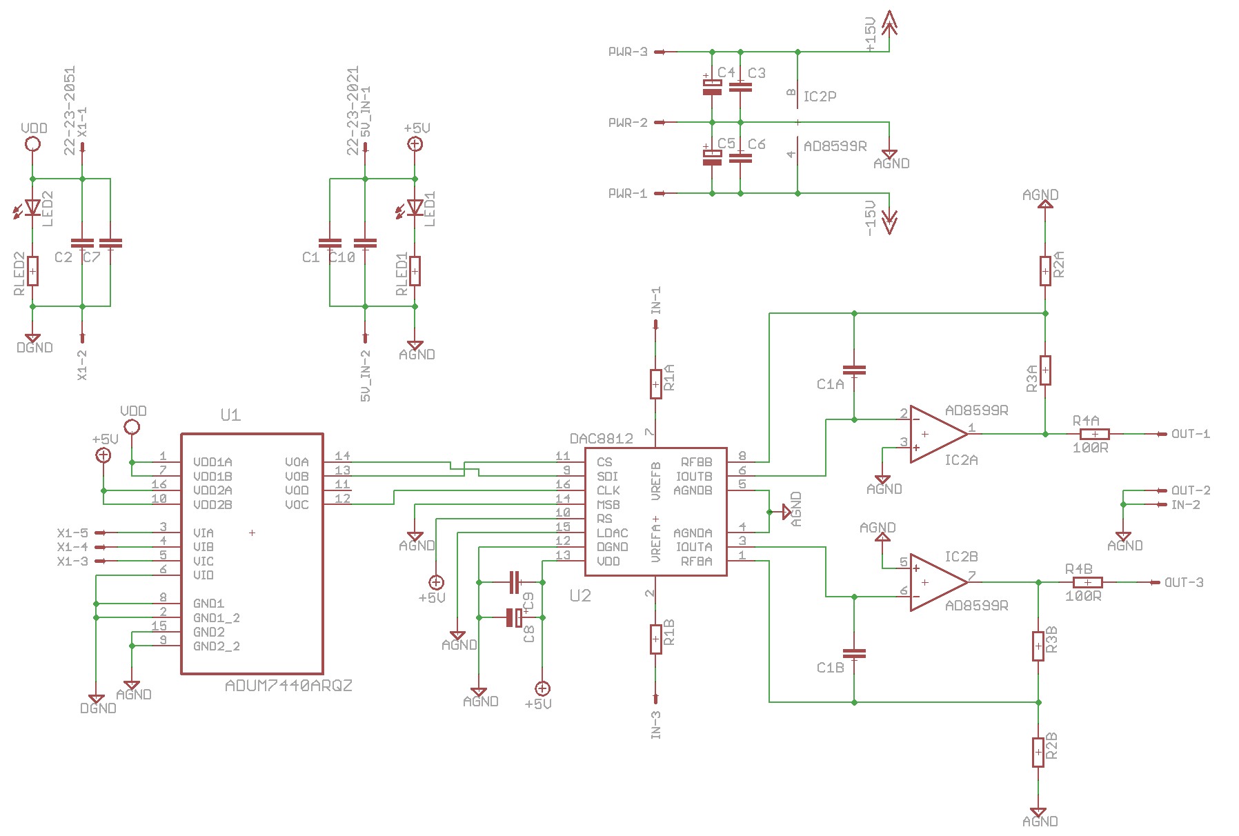
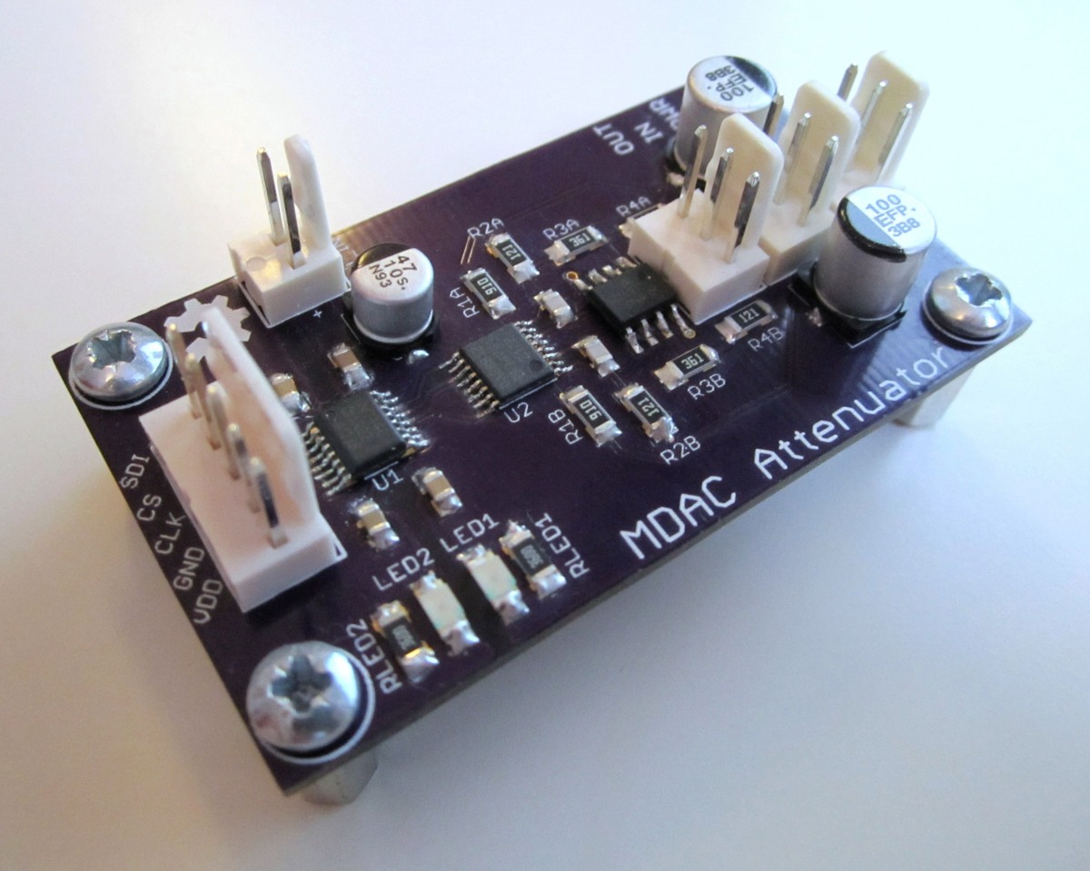
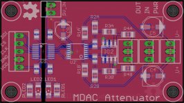
I'd like to improve the attenuator with 12dB gain, the schematic and layout are attached.
Any suggestions??? I'm just not quite sure where to start...
Better PSU?
0805 components and shorter traces?
Mount components on both sides for shorter traces?
A lower noise opamp?
Using my E-MU 0404 for measurements, I think THD is below what I can measure but see the attached RMAA graphs for noise and dynamic range. I have three items on the graphs:
- Loop back = WHITE
- Attenuator with no gain (R2 and R3 removed) = GREEN
- Attenuator with 12dB gain = LIGHT BLUE
I'd like to improve the attenuator with 12dB gain, the schematic and layout are attached.
Any suggestions??? I'm just not quite sure where to start...
Better PSU?
0805 components and shorter traces?
Mount components on both sides for shorter traces?
A lower noise opamp?
Attachments

If I'm not mistaken you have a big fat ground loop in the board (plus a small one) that you should break somewhere. Those are the perils of ground fills.
Other than that, where's your absolute noise level at currently? Doesn't look too bad tbh. An AD8599 is a low-noise part but I'm not sure what sort of impedances it sees here.
Other than that, where's your absolute noise level at currently? Doesn't look too bad tbh. An AD8599 is a low-noise part but I'm not sure what sort of impedances it sees here.
H.Ott tells us that fast boards should have all the Inputs and all the Outputs located at one (compact) edge of the board.
I see "clk". Does that mean this is a fast board?
I see "clk". Does that mean this is a fast board?
Can you point out where? That IC 'U1' is an SPI isolator which isolates the microcontroller from the DAC, 'U2'. There is supposed to be a gap there.If I'm not mistaken you have a big fat ground loop in the board (plus a small one) that you should break somewhere. Those are the perils of ground fills.
Not sure what you mean by that? Is that THD+N? Or just the noise level figure that RMAA gives? RMAA loopback says about -113dB where my attenuator measure -107dB. Does that make sense?Other than that, where's your absolute noise level at currently?
Sorry, I forgot to say, I actually used an LME49720 opamp. Do you think switching to a AD8599 would make a measurable difference? It is 1.1nV/√Hz compared to the LME49720 at 2.7nV/√Hz.Doesn't look too bad tbh. An AD8599 is a low-noise part but I'm not sure what sort of impedances it sees here.
CLK is the SPI control clock signal. The connectors on the isolated left side of the PCB are all for digital control of the DAC IC (using SPI).H.Ott tells us that fast boards should have all the Inputs and all the Outputs located at one (compact) edge of the board.
I see "clk". Does that mean this is a fast board?
Wait....I guess if I can only measure XdB noise level via loopback then if I'm trying to measure an attenuator with +12dB gain then it's likely I'll measure X + 12dB no matter how good my attenuator is!
Perhaps I need better measuring equipment in this case.
Perhaps I need better measuring equipment in this case.
Attachments
create a digital sound file that is recorded at very low levels. But high enough to tell the DAC to stay switched ON.
Replay that very low level signal through your system and read the level of noise in the signal.
Compare changes in your DAC and it's supply by comparing the relative noise to signal levels.
Replay that very low level signal through your system and read the level of noise in the signal.
Compare changes in your DAC and it's supply by comparing the relative noise to signal levels.
Why would this be any different to just using RMAA or ARTA to measure noise?create a digital sound file that is recorded at very low levels. But high enough to tell the DAC to stay switched ON.
Replay that very low level signal through your system and read the level of noise in the signal.
Compare changes in your DAC and it's supply by comparing the relative noise to signal levels.
I don't have RMAA nor ARTA.
I'm a computer noob.
I tried using the Forum suggested file to turn on my sound card.
Now my sound card does not work at all. I can't get it back for any sound.
I'm a computer noob.
I tried using the Forum suggested file to turn on my sound card.
Now my sound card does not work at all. I can't get it back for any sound.
Ah OK, no worries 🙂I don't have RMAA nor ARTA.
I'm a computer noob.
What you are describing would be logically the same as what these programs do. They play a sound via the DAC that then goes into the device you are testing and then into an ADC and back in to the computer. The program then analyses the differences to produce the graphs.
That's not good!I tried using the Forum suggested file to turn on my sound card.
Now my sound card does not work at all. I can't get it back for any sound.
Some, or maybe many, DACs go into mute when the signal drops below a defined level.
If the tested DAC is muted during the "between" signals periods then the test is flawed.
How do you know that the computer controlled testing is measuring a live DAC or a muted DAC?
If the tested DAC is muted during the "between" signals periods then the test is flawed.
How do you know that the computer controlled testing is measuring a live DAC or a muted DAC?
I guess I would just trust that such a widely used application like RMAA or Arta does it properly 🙂How do you know that the computer controlled testing is measuring a live DAC or a muted DAC?
- Status
- Not open for further replies.
- Home
- Source & Line
- Analog Line Level
- How to reduce measured noise floor in my DAC/opamp circuit