what taper pot are you using? Linear or log?
The OP is using an Audio Innovations S300 commercial product. The odds are very long that the volume control is audio (log.) taper
I came across and am uploading the schematic for the MKII version of the S300 amp section. Notice the changes made by the OEM are exactly those proposed by the membership. A lower μ tube (12AU7/ECC82) as the voltage amplifier and long tailed pair (LTP) topology in the phase splitter. All indications point to users other than the OP having "hair trigger" volume control trouble with the 1st version of the product.
Attachments
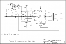
The gain reduction by way of re-designing with the 12AU7 in the first stage is one improvement but the MK II does not use a LTP phase splitter cct. It is a little weird in that there are many HF stabilising networks. It seems that the O/P transformers, as in the MKI version, have their cores too close together and this is causing problems with the design.
The original global feedback was 15k rf and 100 Ohms ri.
It was changed to 3.3k rf and 100 Ohms ri.
And that one fact IS the overall amplifier gain reduction.
Right?
The rest is the lowering of Open Loop gain, and changes to compensation parts and compensation topology, in order to make the amp stable and well behaved with the output transformers, and reasonable speaker loads the amp might encounter.
Probably sounds better than the original.
Anybody have the two different versions to verify the fact?
If I owned the original amp, I sure would change the parts and make it similar to the second version.
Just my opinion.
Last edited:
FWIW, I'd like to see photos of the OP's unit, from both outside and inside. Maybe, just maybe, there's some room for tweaks.
Agreed, but we don't know how sophisticated a bench, if any, the OP possesses.
Another item of concern is the scarcity of the 6GW8/ECL86. While not commonplace, the series heater string variant of the type, the PCL86, can be sourced. Look here. IMO, thought should be given to doing what's necessary to allow PCL86 use.
If I owned the original amp, I sure would change the parts and make it similar to the second version.
Agreed, but we don't know how sophisticated a bench, if any, the OP possesses.
Another item of concern is the scarcity of the 6GW8/ECL86. While not commonplace, the series heater string variant of the type, the PCL86, can be sourced. Look here. IMO, thought should be given to doing what's necessary to allow PCL86 use.
to Flo
"By the way, there is a single 12at7 tube in the line preamp."
One for each channel ?? I suppose.
Walter
"By the way, there is a single 12at7 tube in the line preamp."
One for each channel ?? I suppose.
Walter
to Flo
"By the way, there is a single 12at7 tube in the line preamp."
One for each channel ?? I suppose.
Walter
Given the shared twin triode in the power section, a shared twin triode in the line section is a distinct possibility.
There is only one 12at7 and two 12ax7 for phono.
I decided to go ahead with resistor attenuation before the volume pot since I don't have enough knowledge to modidy the circuit.
The pot tests fine, it's a cheap one but audio grade, so the amp must have been designed for lower voltage level at input
I decided to go ahead with resistor attenuation before the volume pot since I don't have enough knowledge to modidy the circuit.
The pot tests fine, it's a cheap one but audio grade, so the amp must have been designed for lower voltage level at input
Take attention on resistive network.
The Zout of the phono is high so the attenuator must have an high impedance otherwise you lost the bas frequencies
Walter
The Zout of the phono is high so the attenuator must have an high impedance otherwise you lost the bas frequencies
Walter
Maybe I missed it … but I don't think anyone mentioned removing the bypass resistor on the cathode-resistor of the preamp's first stage. That can go a long way to reduce gain. Linearizes things up, too … as a side-benefit.
IF however, 'the sound' is altered in a way dubbed undesirable, then stuffing a little resistor-resistor divider on the input is safe, easy, cheap. It can be done for less than a buck. You could even get “all fancy” and put a switch on it (requiring drills, a switch and so on) that cuts the attenuator in-and-out rapidly. But … now it is getting complicated.
Keep it Simple.
⋅-=≡ GoatGuy ✓ ≡=-⋅
The problem is that we haven't the schematic with 81.
We have seen the phno stage and amp stage. In the middle?
Maybe is a CF.
Walter
We have seen the phno stage and amp stage. In the middle?
Maybe is a CF.
Walter
Take attention on resistive network.
The Zout of the phono is high so the attenuator must have an high impedance otherwise you lost the bas frequencies
Walter
The OP is going to add a padding resistor in series with the volume control. I/P impedance will be raised. There will be no loading the phono section down.
To avoid altering the circuit properties when fitting an attenuating resistor make sure that the overall impedances presented to the following circuit remain unchanged.
An increase in impedance presented to the feeding circuit is unlikely to adversely affect anything, and might even make it a little more 'comfortable'.
An increase in impedance presented to the feeding circuit is unlikely to adversely affect anything, and might even make it a little more 'comfortable'.
In your first posted circuit I would put a resistor in series with the I/P, which is effectively the same as another suggestion of using them in the plugs, this raises the impedance 'seen' by the O/P of the feeding device, (innocuous), and leaves the 47k I/P resistor only slightly less shunted by the feeding source impedance.
GoatGuy,
You are correct.
Removing the bypass cap of the first stage of the preamp will lower the gain of the preamp's first stage
But . . . it will also raise the plate resistance of the 12AX7.
1. With bypass cap, you have 58k rp in parallel with 100k RL
2. Without bypass cap, you have >>58k in parallel with 100k RL.
The RIAA passive network needs to be driven from # 1.
# 2. will change the frequency response of the RIAA network.
That is why I proposed putting a 5751 there. He will get a 3 dB reduction of gain, but essentially no change of the frequency response.
And, you get another 3dB gain reduction in the second stage, for a total of - 6dB.
Easy, neat, and clean.
GoatGuy,
You are correct.
Removing the bypass cap of the first stage of the preamp will lower the gain of the preamp's first stage
But . . . it will also raise the plate resistance of the 12AX7.
1. With bypass cap, you have 58k rp in parallel with 100k RL
2. Without bypass cap, you have >>58k in parallel with 100k RL.
The RIAA passive network needs to be driven from 1.
2. will change the frequency response of the RIAA network.
That is why I proposed putting a 5751 there. He will get a 3 dB reduction of gain, but essentially no change of the frequency response.
And, you get another 3dB gain reduction in the second stage, for a total of - 6dB.
Easy, neat, and clean.
I learned long ago … always defer to the smart people! Thank you.
I just miss Popilin, ridiculously smart, and DF96, who came to be an old sparring 'partner/friend'. AndrewT, too. Sreten and Davada … sigh. Really smart people. Maybe it is the sadness incurred 'cuz of the coronavirus, but I'm just bitterly saddened by the prospect of so many bright lights here going out. The future is getting dim.
⋅-=≡ GoatGuy ✓ ≡=-⋅
Last edited:
GoatGuy,
I am thankful that you are still here.
And I am also thankful for so many others that are still here.
I am thankful and glad that we have some new members too.
I can be a royal pain sometimes (and I have been), and I have made a number of mistakes in my postings, but all in all I try to be helpful.
I remember my times in San Francisco (Summer vacation 1960, High School band on city tour in 1962 at Kezar Stadium 49ers Vikings game; 1965 US Naval Treasure Island 9 months Electronics School; and 3 months in 1968 at Mare Island Naval Shipyards overhauling our destroyer).
It is a great city. In 1965, we walked one day from the bus station on mission and 2nd?, all the way to the ocean in Golden Gate Park (took the bus back).
In 1965, there was lots of electronic surplus on Market Street (too bad I did not have room to store some of that stuff).
Last edited:
If the line amp is a single stage amplification, to get 6 dB attenuation on signal and the pot is 100k you need to put in serie to it another 100k, fix.
But if the pot is 250k, and always you need 6 dB of attenuation, you must add 250k in series.
In this way the frequency answer of the stage is less than original
If the line preamp is a simply CF the solution is less complicated.
This to mantain high the input impedance
I would like to know the lin preamp.
Note: the author saud that the gain is high for pohno and Aux so the problem in not in one part
Walter
Last edited:
- Home
- Amplifiers
- Tubes / Valves
- How to reduce gain in integrated tube amp