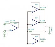
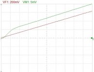
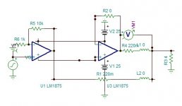
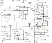
Each paralleled amp equates the voltage of its resistor to be equal to the master's resistor. By this the output current is multiplied here by four. the main amp sees the load as Rload×4. The load sees the impedance of the main amp as Z/4.
Hayk
Attachments
Last edited:
This works only if the amplifiers can be connected at unity-gain. Chip power amplifiers sometimes can't.
On simulator it does work in perfection with a gain of unity.
Bellow is the transient for 10khz 10v
Bellow is the transient for 10khz 10v
Attachments

Last edited:
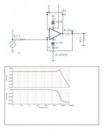
Parallel bridge configuration is widely used to get high power amplifiers by using small chips. The LM1875 gives its best with 8 ohms 15 watts only.
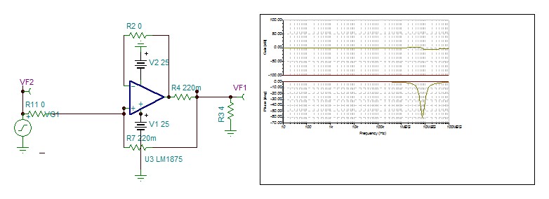
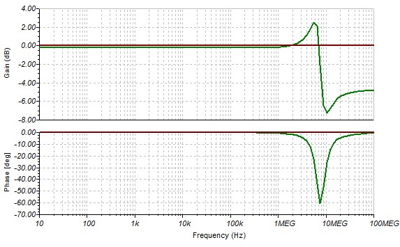
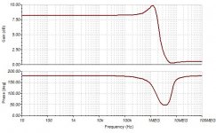
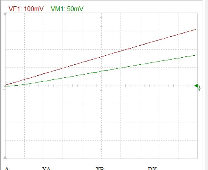
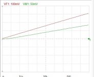
Bellow is the impedance that sees the main driving amplifier. To note that the simulating model doesn't have inductive component of the output impedance, it is fixed for simplicity to 0.1 ohms. This why the high frequency impedance falling to 0.5 ohm is wrong.
Bellow is the impedance that sees the main driving amplifier. To note that the simulating model doesn't have inductive component of the output impedance, it is fixed for simplicity to 0.1 ohms. This why the high frequency impedance falling to 0.5 ohm is wrong.
Attachments
Last edited:
On simulator it does work in perfection with a gain of unity. ...
The datasheet says minimum gain is 10.
Which suggests your simulation model is incomplete.
Attachments

I appreciate your attention about the subject.
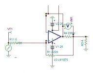
The datasheet also precise that it is loaded 2k. The open loop gain depends greatly with the load. The datasheet also precise that with one ohms in series, it is stable with any capacitive load. In other words, the OLG with one ohm gets considerably reduced to remain stable. How about loading 0.22 ohms! The OLG decreases by far by 10 fold to be stable at unity gain. If an amplifier still oscillate, to feedback by 1k resistor and shunt the inputs by 100 ohms. The gain decreases by ten fold. See applied by Mooly The LM1875 for best
After testing on simulator, it is the positive feedback is the reason of stability.
Last edited:
The stability is perfect but very well damped.
This is modeled with not non inductive resistors worst case and adjusted for perfect stability.
Attachments
Last edited:
Hayk,
Is this needed? Rowlands has marketed amps with multiple chips, at high cost, and others had done this with HP amps too.
HD
Is this needed? Rowlands has marketed amps with multiple chips, at high cost, and others had done this with HP amps too.
HD
Discard the precedant post, wrong circuit.
Attachments

Last edited:
FauxFrench tried to parallel bridge triple pair, it is so difficult to adjust the offset and the gain precisely on each six amplifiers. So I decided to take over his project but in my way. Frankly, I am very glade, as I created two new circuits.Hayk,
Is this needed? Rowlands has marketed amps with multiple chips, at high cost, and others had done this with HP amps too.
HD
Pluto electronics
Linkwitz paralleled two IC power amps for the woofer amp on his Pluto speakers. Schematic is in the post I linked if you scroll down. Look at the literature for the chip he was using, and maybe there is some more helpful information?
Linkwitz paralleled two IC power amps for the woofer amp on his Pluto speakers. Schematic is in the post I linked if you scroll down. Look at the literature for the chip he was using, and maybe there is some more helpful information?
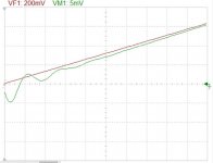
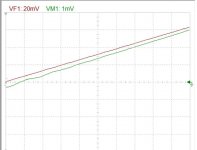
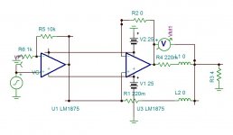
It is also possible to adjust the stability to perfection by adding an inductance to the main's resistance L2 of 100nH. This inductance can be realized by not using non inductive resistor and/or looping the leads single turn. Bellow is without and with. The scale is 50ns.


Last edited:
Pluto electronics
Linkwitz paralleled two IC power amps for the woofer amp on his Pluto speakers. Schematic is in the post I linked if you scroll down. Look at the literature for the chip he was using, and maybe there is some more helpful information?
It looks to be bridged, not paralleled. Thanks for showing there are interesting things.
Attachments

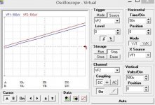
This is 10khz square wave, What the people want better?
Why I have bad face on the thread? Should I stop here?
Every one of those output gain stages should each have their own DCservo amp on them. 😉
See this thread .....
BPA-200 servo problem
jer 🙂
See this thread .....
BPA-200 servo problem
jer 🙂
Last edited:

- Home
- Amplifiers
- Chip Amps
- How to parallel multiple power amps?