As I wrote in another thread I build some speakers based on the Foster FE-103-Sol 8 Ohm drivers. I'm driving this now with a cheap $1 3W amp module and an ipod.
I also own a highly improved Little Bear P8 preamp / headphone amp that I'm using with some grado headphones.
The improvement was done only by changing all caps with MKPs of same value.
Adding bypass and filtering caps, changing the filtering electrolytic's
Connecting the 3W amp module at the LB preamp output results in a volume that ist too loud, so only 10-20% of volume is enough.
How do I modify this Little Bear P8 to become an amp for my 8 Ohm speakers and also be usable for my 32 ohm grado's.
I'm a diy/electronics newbie, but able to, learn, follow instructions and improve sound by try and listening. 🙂
Last edited:
Connecting the 3W amp module at the LB preamp output results in a volume that is too loud, so only 10-20% of volume is enough.
In that case, you only need a power buffer, something that doesn't provide any gain but is capable to drive 8 ohm speaker directly. Since you're using the 3W amp with Fostex and not complaining, i guess what you need is something with low power output: 3-5W.
Now, do you need the power buffer to be tube-based or solid state?
If tube-based, look at the attachment.. taken from tubecad journal here Tube CAD Journal: Tube balanced phono stage, July 1999
It's still lacking the power supply schematic but that comes after you decide: Tube or SS? Keep in mind that tube-based amp tends to be more expensive that SS-based amp.
I believe that Little Bear P8 has enough gain to drive that EL84 amp to full output, assuming your source is digital like an iPod or CD player. It's the one with 6N3 and 6N5P tubes, right?
If solid state is okay, i'm sure the guys on the chip-amp section can have better suggestion. Just ask for a simple power buffer with 3-5W output. I personally would prefer solid-state for that kind of output power.
Attachments
Thanks for the EL84 solution. The LB should have enough gain
My source would be a dac.
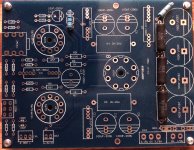
here are some images of the pcb


32 ohm - 600 ohm output impedance:
300 MW (600/300 Ohm)
350 MW (120 Ohm)
250 MW (32 Ohm)
My source would be a dac.
here are some images of the pcb
32 ohm - 600 ohm output impedance:
300 MW (600/300 Ohm)
350 MW (120 Ohm)
250 MW (32 Ohm)
Last edited:
The transformer is providing:
170 V (100ma),
3.15V-0-3,15 V (2a)
6,3 V (1a)
the 170V are rectified and filtered by 4x150uF electrolytic caps.
here is another version that I have without preamp output:
It would be easier for me, if someone can mark the suggestions and needed modification on the picture, please.
But always still maintaining the 32 ohm headphone output.
Attachments
I think you mean 300mW? This is a headphone amp, not a power station.dacster said:300 MW (600/300 Ohm)
Be aware that 'I have a preamp; can I turn it into a power amp?' is a question of the same type as 'I have a bicycle; can I turn it into a car?'. In both cases the answer is 'yes, but there are better ways of achieving the same end result'.
I think you mean 300mW? This is a headphone amp, not a power station.
😀 sure mW, not Mega-Watt 😱
The problem is, that an real power amp above 3-5W would be to much for my speakers and listening volume.
Last edited:
Be aware that 'I have a preamp; can I turn it into a power amp?' is a question of the same type as 'I have a bicycle; can I turn it into a car?'.
Maybe not a car.. just a lawnmower engine-powered bicycle. By lawnmower engine, i am referring to small power buffer 🙂
dacster, i am just so happen to be in the process of making an OTL headphone amp as well.. and the idea of having a simple power buffer to drive a speaker intrigues me as well.
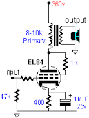
hopefully this will get the "idea and suggestion" ball rolling. See below for a suggestion of a simple power buffer. Basically a Class A push-pull EL84 (or 6BQ5). Vin is where you feed your Little Bear P8 Preamp output. Just to be clear, we are not touching the internals of your P8. This power buffer will be on a separate chassis, complete with its own power supply.
An externally hosted image should be here but it was not working when we last tested it.
As you can see, with 7 Vpeak input, we are getting also close to 7Vpeak output. 7Vpeak to 8ohm speaker is 3W. Just what you need.
I1 is a constant current sink.. You can make it using LM317 and 15 ohm resistor, read about it on the link below:
LM317 / LM338 / LM350 Current Regulator Calculator and Circuits
ballpencil: Thank you very much! This is exactly what I need. Not changing the LB P8 I will always have the option of connecting an power amp for other speakers in future.
So I try to collect the parts and try to rebuild 🙂
So I try to collect the parts and try to rebuild 🙂
Simulation like above means every part is identical.. real world, however, is not. So.. it is a good idea to replace R6 and R7 with a 25ohm trimpot.. and connect 1 ohm resistor on each cathode to measure the current from each EL84 to make sure they are equal. Equal current from each EL84 is essential, not only to get the best SQ.. but also to increase the power supply ripple resistance, so you don't hear any hummmmm on your sensitive speaker.
The schmatic above is nearly identical to the output stage on Bruce Heran's amp on link below
http://diyaudioprojects.com/Tubes/EL84-Mini-Block-Amps/
The schmatic above is nearly identical to the output stage on Bruce Heran's amp on link below
http://diyaudioprojects.com/Tubes/EL84-Mini-Block-Amps/
Last edited:
Hi,
I sometimes muse on the idea of converting a valve amplifier with
enough voltage swing but not enough current to a feedforward
design by bolting on a unity gain transistor output stage, and
using a bridge to allow the valve amp to cancel buffer distortion.
rgds, sreten.
I sometimes muse on the idea of converting a valve amplifier with
enough voltage swing but not enough current to a feedforward
design by bolting on a unity gain transistor output stage, and
using a bridge to allow the valve amp to cancel buffer distortion.
rgds, sreten.
The transformer is providing:
170 V (100ma),
3.15V-0-3,15 V (2a)
6,3 V (1a)
the 170V are rectified and filtered by 4x150uF electrolytic caps.
here is another version that I have without preamp output:
It would be easier for me, if someone can mark the suggestions and needed modification on the picture, please.
But always still maintaining the 32 ohm headphone output.
Where did you buy these boards! I am looking for one of these!
- Home
- Amplifiers
- Tubes / Valves
- How to modify the Little Bear P8 preamp to become an amp?