I am one of the ones who learned electronics backward. First I learned how to fix them then I learned why what I did fixed them, so there are holes in my education. To the point. Recently I completed a very nice sounding 20WPC all triode power amp using 6AS7s for the outputs.🙂 I then bought a used HD Meter and a new Audio Sig gen speced at .018 % HD. The meter confirms the Generators output. So I decided to measure the stage by stage distortion in the amp (it has no feedback). The first voltage amp showed a distortion of 0.4%.🙁 It is one section of a 12AX7, 180 plate supply, 82K Rp, 470 ohm Rk, 470K Rg, with a .04 input and output coupling caps and a 2 ufd Ck. Measurement shows a Vg of ~40 ( 50mv in 2V out). with .4 % distortion.
I then breadboarded that stage. Yep .4 % is as low as I can get it at any reasonable amplification factor.
Now the questions. Is that an unusual amount for one stage? Are HD artifacts additive as you add stages. I assume they are? My Dyna PAS2 specifies HD as being "below that measurable by (back then) modern equipment." To me 0.4% means if I had 4 stages like the 1 stage in my amp the distortion for the amp would be ~1.6 %. What am I doing or thinking wrong? Is .4% a good number for one amplifier stage? 1.6% (.4 x4) is certainly not a good figure for a preamp.😕 Its all very possible that I should quit nit picking and enjoy its openness and what I describe as clarity.🙂
Thanks
Ned
Last edited:
No feedback usually means higher measured distortion, and the distortion will be somewhat proportional to level. Later stages will have larger signal levels, and so higher distortion. The THDs of the stages don't just add together, though.Is that an unusual amount for one stage? Are HD artifacts additive as you add stages.
Last edited:
Your (unnamed) HD meter also contributes significant loading to a 12AX7, already heavily loaded by its 82K anode load. Actual results will be somewhat better.
All good fortune,
Chris
All good fortune,
Chris
Your (unnamed) HD meter also contributes significant loading to a 12AX7,
already heavily loaded by its 82K anode load.
You can use a high impedance attenuator (say 1M/100k) for the tube stage load,
and measure the distortion across the smaller resistor, so the meter doesn't add
any significant loading to the tube. Any loss of resolution due to lower signal levels
doesn't matter much with tube levels of distortion.
Last edited:
try a higher anode load, larger cathode resistor, and a larger cathode bypass cap. Directly cascade this output into a cathode follower made from the other half of the 12AX7. Maybe even try an LED or a pair of diodes instead of the cathode resistor if you have any on hand of an appropriate voltage drop.
Something like 120~150k anode resistor and 1200~1500 cathode resistor might give you better THD, but a bit lower drive capabiltiy, so you will want to isolate it from the load with a good follower.
Something like 120~150k anode resistor and 1200~1500 cathode resistor might give you better THD, but a bit lower drive capabiltiy, so you will want to isolate it from the load with a good follower.
That confused me for a moment: Vg means the voltage on the grid.nsheats said:Measurement shows a Vg of ~40
No. Poor, perhaps, but not unusual.nsheats said:Is that an unusual amount for one stage?
HD? Assuming you mean harmonic distortion, then no it doesn't simply add up. It is more like multiplying, but with phase being relevant too. If you had 1% distortion in two stages then the total distortion could beAre HD artifacts additive as you add stages.
a. 1.01 x 1.01 -1 = 1.0201 -1 i.e. 2.01%
b. 1.01 x 0.99 -1 = 0.9999 - 1 i.e. 0.01%
or anywhere in between. In reality, somewhere around 2% is likely.
Note that it would be quite difficult to make several stages all with 1% distortion because distortion depends on both the circuit and the signal level, so later stages are likely to have more distortion.
Hello,
The thing that I notice most about the sound quality of tube amplifiers is noise. Noise is the first thing that I measure.
At the breadboard stage of design clip on your probes and look at noise and distortion products, adjust the supply voltage(s) and operating point for minimum noise and distortion.
Hiss is never good. Hum and buzz is the worst.
Low levels of THD and IM will be masked by the program material.
The vast majority of the distortion comes from the speakers.
Thanks DT
Without negative feedback you are at the mercy of the Vg^1.5 law for all thermionic devices - the current is a non-linear function of the grid voltage, typically about 3-halves power law. (google Childs law). So you get more distortion the higher the signal level without any feedback to tame the non-linearity. Valve distortion produces all harmonics, but more power in the lower order ones.I then breadboarded that stage. Yep .4 % is as low as I can get it at any reasonable amplification factor.
Now the questions. Is that an unusual amount for one stage?
You should be able to get lots more voltage swing at a lower distortion out of that 12AX7. I think that I remember a test with 9Vrms @ 1% (+/- 12.7V peaks). That would be 4.5Vrms at 0.5%, which is far more than the 2V (rms?) @ 0.4% that you got.
~ 1mA current, ~ 90V on the 12AX7 plate, 82k plate load, 180V B+, 90mW plate dissipation, and ~ 0.47V cathode bias is not where I would run a 12AX7. At only + 0.47V on the cathode, and 0V on the grid, the grid is practically sitting in the cathode's electron cloud. Unless I missed something, is that the circuit you described? Go for a little more current, more plate voltage, and more cathode bias.
By the way, two inverting stages that each have 0.4% 2nd Harmonic and are run in series, can cancel, and have 0.0% 2nd Harmonic (will never be exact cancellation, but close). Say that one stage is long in the positive alternation, and the other stage gets that signal. But the other stage would be long in its positive alternation, but its inverted output cancels the first stage's 'long' signal (opposite phase).
Of course, the second stage has to have much more voltage swing, since its gain follows the signal from the first stage (Its design has to be different).
And when I say 0.4% 2nd harmonic for each stage, I mean 0.4% at the signal level that each stage in the cascaded 2 stage amp will have.
This is serial cancellation of the 2nd harmonic, and can happen in a 2 stage SE amp. But there is no free lunch. The problem is, the second stage has to run an output transformer and a loudspeaker. Neither the output transformer, nor (especially) the loudspeaker have constant impedance from 20Hz to 20kHz. That means the plate load is changing versus frequency. The distortion is dependent on the plate load. A simple resistor load line is one thing. But changing the slope changes the distortion. Oh, . . . and did I say that the load on the output stage can have not only resistive, but can also have capacitive, and inductive elements. Those capacitive and the inductive parts each will create Elliptical Loads. Think about what an ellipse looks like when it traces above, crosses, below, crosses again, and goes above that resistive load line.
But do not worry too much about that, I have heard so many excellent sounding 2 stage SE amps, and enjoyed listening to them.
Push Pull deals better with Ellipses (especially with triodes, triode wired beam power, and triode wired pentodes, and Ultra Linear beam power and UL pentodes). The triode has low plate impedance, and the rest have (local) negative feedback (triode wired, and UL). That local feedback lowers the plate impedance of those beam power and pentodes. That all occurs Before Global Negative Feedback. . . . But that is another subject.
The 12AX7 is capable of much better performance than you are getting. I would experiment with a different operating point.
Triode / Pentode Loadline Simulator v.1.0 (20161216 www.trioda.com)
Use ECC83 and put in your operating points. Then increase the bias to -1 volt and watch the distortion go down by a factor of 10.
I don't know the degree of accuracy of the distortion calculation but, I have found it useful in selecting operating points.
Steve
......180 plate supply, ...( 50mv in 2V out). with .4 % distortion.....
Counting on thumbs--- a happy triode will swing a peak near 20% of supply, at about 5%THD. And THD will scale down nearly as signal level.
180V * 0.2 = 36V peak @5%
Assuming your "2V" is RMS, that's like 3V peak. Which is 1/12th of 36V peak. So THD will be near 5%/12. Which is near 0.4%.
My rule of thumb for bog-standard triodes is: take the RMS output voltage and divide by ten -that's the % distortion you might typically obtain. So for 2V output I would expect something in the region of 0.2% distortion
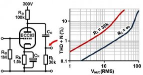
Here's a 12AX7 stage similar to yours; you're definitely in the ballpark.
Here's a 12AX7 stage similar to yours; you're definitely in the ballpark.
Attachments
Fortunately in a grounded cathode triode stage there is usually lots of negative feedback from the anode voltage so the 1.5 law is not a huge problem.Mark Tillotson said:Without negative feedback you are at the mercy of the Vg^1.5 law for all thermionic devices - the current is a non-linear function of the grid voltage, typically about 3-halves power law.
Higher idle current means lower distortion. There are more linear tubes than the 12AX7 (I consider it a guitar amplifier, where warm distorted sound is a benefit). Try a 6DJ8, it has lower gain, but it is much more linear.
To be fair the 12AX7 is more linear than the 6DJ8 as long as you have enough supply voltage, and keep the load above 100k. But the op only has 180V, so yeah.Try a 6DJ8, it has lower gain, but it is much more linear.
Last edited:
The ECC83/12AX7 is quite linear when properly used, which means a high anode impedance. People who can't be bothered to get it right will be better off using lower mu valves which can deliver sufficient linearity when chucked into any old circuit. Of course, this all gets turned around for guitar amps where distortion is required; lazy people can just throw in a 12AX7 and know that they will get lots of gain and clipping without having to actually design a circuit.
check out PDF files in post #82 under
https://www.diyaudio.com/forums/sol...ooks-overview-google-books-9.html#post6707846
https://www.diyaudio.com/forums/sol...ooks-overview-google-books-9.html#post6707846
- Home
- Amplifiers
- Tubes / Valves
- How to measure THD