Here I described how to remove a dustcap
https://www.diyaudio.com/community/threads/how-to-remove-a-dustcap.397165/
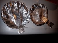
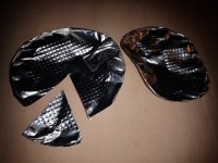
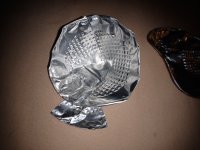
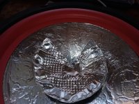
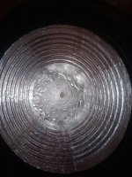
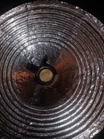
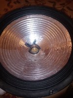
Now I show an easy way to make a metal whizzer cone or double cone
For a flatter double cone cut one tart alike piece out of an eigth of the round aluminium foil.
For a more steep cut out one fourth of it or more.
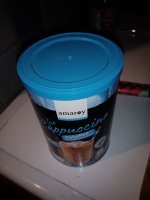
The diaphragm is made out of thick aluminum often found for packing coffee
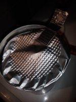
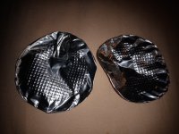
The diaphragm does not look "nice" but is functional. And has a "fuzzy logic" structure. The more it has wrinkles the more it is stable.
As the cone is glued together it has also some damping.
https://www.diyaudio.com/community/threads/how-to-remove-a-dustcap.397165/
Now I show an easy way to make a metal whizzer cone or double cone
For a flatter double cone cut one tart alike piece out of an eigth of the round aluminium foil.
For a more steep cut out one fourth of it or more.
The diaphragm is made out of thick aluminum often found for packing coffee
The diaphragm does not look "nice" but is functional. And has a "fuzzy logic" structure. The more it has wrinkles the more it is stable.
As the cone is glued together it has also some damping.
Attachments
-
 IMG_20230404_194049.jpg169.9 KB · Views: 165
 -
 IMG_20230404_194103.jpg337 KB · Views: 159
 -
 IMG_20230404_194118.jpg394.2 KB · Views: 138
 -
 IMG_20230404_194422.jpg444.5 KB · Views: 155
 -
 IMG_20230404_194456.jpg452.4 KB · Views: 154
 -
 IMG_20230404_194529.jpg439.7 KB · Views: 142
 -
 IMG_20230404_194539.jpg428.2 KB · Views: 181
 -
 IMG_20230406_095825.jpg457.9 KB · Views: 182
 -
 IMG_20230406_095835.jpg494.9 KB · Views: 176

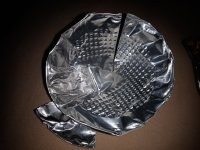
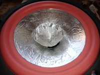
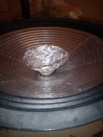
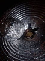
In Germany I use "Pattex repair extreme" glue. But any glue for metals will do. Just take care when gluing the whizzer to the voice coil that no glue drops into the voice coil gap as this is the worst that can happen.
The named glue does not tend to drop. It's more thick.
Just press the ready made whizzer, glued together a day before onto the voice coil gently and form the aluminium of the whizzer as it attaches to the coil you can see and feel the round form of the voice coil.
If it matches closely to the voice coil you can use only the amount of glue in one line just enough to fix it.
Put some small stone to keep whizzer down in contact for the duration of glueing process
You can read it here
See citation of D.A Barlow on sandwich cones:
https://www.diyaudio.com/community/...how-off-my-new-18in-build.365764/post-6741724
In my eyes:
Diaphragm induced distortion gets dramatically down
Everything sounds more correct
Impulse reproduction is much more better
See citation of D.A Barlow on sandwich cones:
https://www.diyaudio.com/community/...how-off-my-new-18in-build.365764/post-6741724
In my eyes:
Diaphragm induced distortion gets dramatically down
Everything sounds more correct
Impulse reproduction is much more better
The aluminium foil is just simple foil used in the household. Glue is simple glue which fits for paper and metals.
You cut the foil into pieces (form of cake pieces) put thinly the glue on the backside of the foil an then fix it with the use of your fingers to the diaphragm beginning from the outer edge. I am used to do this since the year 2000. I had for ten years a website online exactly describing how this is done with thinner foil from the gold smith but it seems to be too much work for the most Do it yourselfers to try this tweak out. As I (nearly) never found anyone reproducing this method.
From theory it is known that the combination of metals and paper can bring a lot more stiffness to the diaphragm (known since the 60ies, but history of loudspeaker building describes this in patents since the 30ies of the last century - it means right from the beginning of loudspeaker production of the dynamic type). For germany it was Dr. Emil Podzus (aluminium foil and hard foam), later it was english speaking D.A. Barlow in the 60ies with duraluminium sheets and expanded polystyrene of thick quality. In germany these aluminium foiled loudspeakers are known as Podzus-Görlich loudspeaker drivers. Mr. Görlich was helping out as a young man at the factory of Mr. Podzus. He later produced these diaphragms with aluminium foil and hard foam. He does it until today.
I measured the loudspeaker diaphragms paper + aluminium very often. One sided and both sided (last means it is a sandwich-cone). Coating of the driver on just one side brings resonances down - makes the speaker sometimes more linear - but always the loudspeaker driver becomes much more stiff and has therefore a significant better impulse reproduction.
Best is this checked by ear while covering one driver with aluminium foil and leaving the second stereo speaker undoped. You can then use your balance knob on your amplifier for an A / B listening test.
Here about the theory:
D.A. Barlow: The Development of a Sandwich-Construction Loudspeaker System. Page 159-171. From the AES anthology of articles on loudspeakers, article written 1970.
Citation begin (page 160):
"As paper cones are thin, these resonances are bending modes. The stiffness of a material in bending, for any given geometry and edge condition, is proportional to Young`s modulus and the cube of the thickness, ignoring variations in Poisson`s ratio. ... On this basis, paper is much stiffer than metals (except beryllium) in spite of its much lower modulus, and lower density materials such as expanded plastics are even stiffer, as may be seen in Table. A method of obtaining still greater stiffness is sandwich construction. ... In bending, the maximum stress and strain occur at the outer fibers, the material at the neutral axis being unstressed. Better use of material can thus be made by concentrating it at the outer fibers. A familiar example is the tube. In the case of large areas, the same effect is obtained by using a thin high-modulus material for the outer surfaces, and a light-weight material or form of construction for the core. ... This sandwich will of course be much stiffer than the same total weight of either material used separately. The skin material should have the maximum ratio of modulus/density. Beryllium, the best material, is impractical due to difficulty of rolling and possible toxicity, so aluminium is the obvious choice. The core should be as stiff as possible in the thickness direction and have minimum density. Honeycomb aluminium or impregnated paper are frequently used in aircraft construction and could be used for flat diaphragms."
Citation end.
For sure you lose a little bit of efficiency just only looking at the frequency response. No doubt.
But, the bending of the diaphragm in a weak driver "eats up" the original impulse - taken this into consideration you gain with a stiffer cone efficiency and get a cleaner signal.
If you can construct a driver from scratch you can make the diaphragm lighter than only using paper.
But, the bending of the diaphragm in a weak driver "eats up" the original impulse - taken this into consideration you gain with a stiffer cone efficiency and get a cleaner signal.
If you can construct a driver from scratch you can make the diaphragm lighter than only using paper.
Small bluetooth box with do it yourself double cone
https://www.diyaudio.com/community/...loudspeaker-sandwich-cone.402917/post-7536581

https://www.diyaudio.com/community/...loudspeaker-sandwich-cone.402917/post-7536581
Added do it yourself double / whizzer aluminium metal cone to 25cm driver from post
https://www.diyaudio.com/community/...loudspeaker-sandwich-cone.402917/post-7499239

https://www.diyaudio.com/community/...loudspeaker-sandwich-cone.402917/post-7499239
Attachments
What software are you using for your 'waterfalls'?
I note the 'time' axis is in 'Periods', which is how we did PAFplots. No one else did it that way, everyone else doing KEFplots which are the common or garden 'waterfalls' today.
And I'm puzzled by your 'frequency response' curves which look like they were done in a normal reflective room, while your 'waterfalls' look lik they were done in an anechoic. You need an anechoic to get the resolution you see at LF on a PAFplot.
=============================
BTW, Don used normal Aluminium foil but it was stuck on with Epoxy. We had a cupboard full of Epoxy formulations, some of which set VERY quickly. This was before the days of '5 min Epoxy'.
One useful trick on a Double Cone unit is to use a hard glue for the whizzer and a soft, rubbery glue for the main cone. This would probably help with your resonance at 5kHz
I will see what Arta offers for waterfall presentation to choose. I used simply what Arta in Demo mode spit me out routinely.
For the glue I am not innovative. I do not use epoxy but standard glue like Uhu or Pattex.
While glueing the whizzer I take care that it is done spaced closely keeping the film as thin as possible. Using contact glue method letting it pre dry. My thinking is if the film is thin the properties of the glue become less dominant.
My experience using EQ is that the occurring resonance can be tamed by linearizing. The one at 5k could potentially be eliminated.
I always measure fullrange drivers in the near field of 10cm on axis. Multi way speakers would need bigger distances and then you have to think about getting good circumstances for the measurement setup.
The frequency response measurement is the same data like the burst decay plot. No separate measurement.
I use the smallest amount of smoothing 1/24. So you can see also peaks in the response better
Last edited:
- Home
- Loudspeakers
- Full Range
- How to make a whizzer cone