I speak English as a native - I am English! That is precisely why I was confused.Destroyer OS. said:I'm talking about the impedance of the noise, and the concerns of it's fluctuations.
Sorry if I don't explain well for non-first english speakers.
Noise does not have an impedance. However, a noise source will have an impedance - exactly like any other signal source. However, in many cases the noise source will have exactly the impedance the circuit would have in the absence of noise. So adding noise or interference to a circuit will not change circuit impedances or circuit Q.
A CFL may produce noise. The impedance of the CFL will be the same whether it is noisy or not. It is not the noise from the CFL which may or may not affect circuit Q, but the presence of the CFL in the circuit.
I'm not going to argue over nothing, please don't yank my chain. Nothing is different, source increase in impedance enhances Q, and if it's not 60hz, it's basically noise for our concerns.
If you're trying to validate something that makes you obsessively specific, throw a schematic or idea at us; the forum doesn't progress well from redundancy circles.
If you're trying to validate something that makes you obsessively specific, throw a schematic or idea at us; the forum doesn't progress well from redundancy circles.
I'm not going to argue over nothing, please don't yank my chain. Nothing is different, source increase in impedance enhances Q, and if it's not 60hz, it's basically noise for our concerns.
If you're trying to validate something that makes you obsessively specific, throw a schematic or idea at us; the forum doesn't progress well from redundancy circles.
Since you are using a capital Q, I assume you mean Quality Factor. In that case, an increase in resistance always decreases Q.
Unless you are suggesting that reducing Q is an enhancement, which is contrary to the usual meaning in both technical and common English.
Sync, I am curious if you built it. 🙂
Had to wait on a part or two.
Hopefully weekend.
Will make a change or two.
I will wire one of the caps diaginally across the choke.
I'm trying to find and additional choke(s) and wire
it in series with the first choke and also run another
cap diagonally across it.
This is based on my own research where I discovered
our own RNMarsh has done some prior research on this.
So, based on his work, I'll adabt it for my first felix project.
The advantage of running a cap diagonally across the choke
is that you effectively block two frequencies.
Addiing another choke with a diaginally wired cap around it
you block four frequencies.
I'm going to add some higher value MOVs up front and a fuse.
I probably won't cross each wire between caps.
I've got a test box, but trying to find some inexpensive
other boxes to repurpose. Like something at a garage
sale for a buck or two.
I'm slow a getting things done, because I try to understand
what is going one, look around see what others are doing
learn, think about it, look around some other areas,
gather parts along the way then crank it out.
I had to find my little swedging tool and the beat goes one.
Thanks Seavan for asking. I"ll post some pics along the way.
Vivee, load resistance lowers Q, source has the opposite affect.
Sync, that was an idea I had for a bit, but I've been alterted that it will cause some issues as well. Plus "block" is a bit of a strong word, attenuation is the only thing happening.
Sync, that was an idea I had for a bit, but I've been alterted that it will cause some issues as well. Plus "block" is a bit of a strong word, attenuation is the only thing happening.
Block
Destroyer,
Yes, attenuate more properly discribes the intent.
Y'all:
Do you know if it is worth while to put a DC blocker
on the front end of the Felix?
To put something like this in the front end
which I saw on Ray's page:
http://www.raylectronics.nl/pictures/balanced_filter/Balanced_filter_3.jpg
Thanks,
Last edited:
Vivee, load resistance lowers Q, source has the opposite affect. .
I disagree, but then I find your terminology so loose you could be meaning anything.
I disagree, but then I find your terminology so loose you could be meaning anything.
Actually you're correct. I mixed the two up. I knew Q is better as a filter with high source impedance. I remember which is preferable, so I have notes on this stuff written down. I've muttled an understanding of this up. High source impedance is why low load impedance isn't the an issue nullifying the filter.
This is a parrallel filter so high Q is bad. The higher Q is, the more impedance the filter will tend to have, making it less effective.
You've reversed series and parallel LC circuits. Series you want high Q, say at 60hz. Parallel you want low Q. That is when using an LC in this AC mains application. We aren't trying to bandpass 60hz... Not on AC line...
I'm really sorry to add so much confusion. My memory isn't terribly good with specifics all the time. But what I'm entirely certain about is how much of a fantastic improvement power conditioning is, even with a minor LC setup like Felix.
I found a lot of RFI-filters laying around at work, how do you guys think it would work for power-conditioning? See attachment. We normally use them to prevent noise going back to the grid from frequency-converters, but could one connect them the other way round, to prevent noise from going into my audio equipment? They would be a Zero-$ investement to me, so if they could work, that would be great!
Regards
- Bjørn
Regards
- Bjørn
Attachments
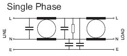
Commercial power filters tend to help at some frequencies, hinder at others. I'd say just try it and find out, if it's not hard to do.
Thanks Keantoken! Will give it a try! 🙂 What about direction, would you have connected it opposite of what's in the schematic? As I said, we use them to stop noise going from frequency-converters and back into the grid.
Regards
- Bjørn
Regards
- Bjørn
I think the source and load both benefit from using it in the right direction. Using it backwards might just pollute the earth line.
Try to find a couple used medical grade line power noise filter & iso trans units. It would take two of the small ones like I have. I have a couple big boat anchor ones left from when I used to do sound & lighting for live shows. Dimmers played hell on everything. Unfortunately for every 15 amps in we only got about 8 back out, but it was really clean. I should put my photos in Photo Bucket or somewhere so I can post one in here. The medical iso trans filters have some rather unique massive R cores, with two added C cores with partial windings that run through two cap banks of beer can electrolytics. (big Foster's Beer can sized). The are the only electrolytics I have ever seen with an ERS & Q that rivals film caps. After replacing 3 of them, I'd advise just buying a good rack mount conditioner! You will want separate filtered power banks so you do not get intercomponent interference. That is where most of the computer UPS systems fail miserably. The medical filter has a two secondaries each with small separate C core side winding that runs through the cap banks. Not something I could make myself, at this point! You would go mad witching wire into coils through those multiple cores. I know I would!
The diagram is already labeled.
Just wire it up that way.
If you can install it inside a metal case that is directly bolted to the Chassis the it wil be even better.
For best performance that metal case should have no long slots at edges and joins.
Just wire it up that way.
If you can install it inside a metal case that is directly bolted to the Chassis the it wil be even better.
For best performance that metal case should have no long slots at edges and joins.
ROFLMAO
ROFLMAO
somebody has to volunteer to explain how to do one's own research.
ROFLMAO
I was planning to make a power conditioner for my amps, but I don't like the idea of soldering chokes and caps to a breadboard and using it with mains voltage. Instead I would be using ready made power line filters. So it's going to be less diy, but more safety.
From Mouser I found some modules, that are in good price range and have nice current ratings. I wanted to ask, if one could use them to make a power conditioner or am I looking completely wrong products.
10EH1 TE Connectivity / Corcom | Mouser
851-05/005 Qualtek | Mouser
4EHZ1 TE Connectivity / Corcom | Mouser
In the data sheet of the first two it says EMI filter. Last one is specified as a RFI filter. I think RFI filter is more what I'm looking for, but I'm not sure.
I'm also very happy to hear other suggestions, that could be used and even better, if they are sold in Mouser. 🙂
I don't see any benefit from the top one over the others. The second is best at the very highest frequencies, but the last one is better in the ultrasonic range.
I would go with the second one. If I were worried about problems that might be caused by a filter, I would go with the third one. The plot for the second one shows resonances which may be counterproductive.
I would go with the second one. If I were worried about problems that might be caused by a filter, I would go with the third one. The plot for the second one shows resonances which may be counterproductive.
- Status
- Not open for further replies.
- Home
- Amplifiers
- Power Supplies
- How to make a power conditioner