I would check for glitching of the amplifer output during current limiting when the SOA protection is attached to the VAS output. Look out for oscillations and instability since the amplifier loop is effectively shortened when the protection fires.
Another possible solution as long as you have enough voltage between the VAS outputs is to use a triac and opto. Cordell Page 328.
Another possible solution as long as you have enough voltage between the VAS outputs is to use a triac and opto. Cordell Page 328.
Here's a two slope arrangement derived from Michael Kiwanuka's design procedure, plotted against a 50degC derated SOAR of your device. Since Vref=0, Z1 and R6 aren't required. Should you desire the inferior single slope, merely remove R4.
Brian.
Brian.
Attachments
Thank you very much for your SOAR sheet Pingrs,
and thank you mcd99uk and scopeboy for your help,
I've a problem the devices I'm using they aren't BUZ901/906D, they are BUZ901/906P, I've added the D to the models accidentally. What I have to change? BUZ901/906P pair has Pdmax = 125W and Idmax = 8A, half of the BUZ901/906D devices, could you help me here what I've to change in the VI limiter to meet the SOA requirements for this output pair?
Thank's a lot this SOAR sheet is just great, sorry for having the models with the wrong designation I will change it.
Best regards,
Daniel
Attachments
Thank you very much Brian, you helped me a lot I will post the results of the simulation of the VI limiter later.
Best regards,
Daniel
Best regards,
Daniel
Please do, I'd be very interested. Apart from Mike's simulations in Multisim, I've not yet seen an accurate simulation of a VI locus anywhere.
Brian.
Brian.
Did you look at any of the SOAR plots in the spreadsheets I offered to the Members?
These were a development of the Bensen spreadsheet interpretation of David Eather's paper.
These were a development of the Bensen spreadsheet interpretation of David Eather's paper.
Hi everyone and thank you all for your great help,
This night was dedicated to VI limiters,
I've tested the circuits with the values you've gave to me Pingrs, but the result wasn't very good, the circuit doesn't limit the current, it only limits the current if I remove R5 and C1, and I don't understand why, can you help me here?
It's very strange but when I remove the base to emitter capacitors I don't have oscillations, with them I have oscillations, this is really strange because the capacitors should be there to prevent oscillations during current limiting, and not to cause them, but the LTSpice simulator is showing me this, why?
With the values you've gave to me Pingrs, I have lower THD at 4ohm compared to the values I have with a simple current limiting circuit, like the one I was using before, but I only can drive loads of more than 3ohm, a real world speaker can have 2ohm or less at low frequencies, right?
I've made another single slope VI limiter based on the one presented on figure 15.4, page 330 of Bob Cordell's book, but I've removed the capacitors also, the limiter doesn't work with them.
Why the base to emitter capacitors are causing oscillations, instead of preventing them, I'm doing something wrong? This is really strange 😕
You can simulate my circuits and see this happening.
🙁
Best regards,
Daniel
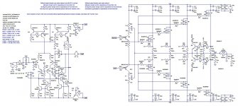
Attachments
-
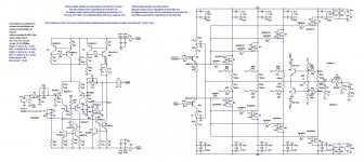 amp7_tmc_hb5_bd10_prot8.jpg221.3 KB · Views: 198
 -
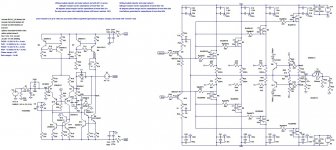 amp7_tmc_hb5_bd10_prot7.jpg222 KB · Views: 215
 -
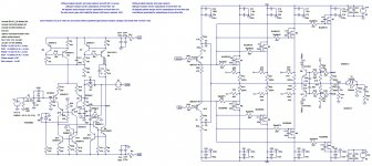 amp7_tmc_hb5_bd10_prot6.jpg234.6 KB · Views: 209
 -
BC3x7_40 Models.txt1.2 KB · Views: 77
-
Cordell Models.txt19.2 KB · Views: 85
-
Amp7_tmc_hb5_s_bd10_prot8.asc26.8 KB · Views: 81
-
Amp7_tmc_hb5_s_bd10_prot7.asc26.8 KB · Views: 80
-
Amp7_tmc_hb5_s_bd10_prot6.asc27.4 KB · Views: 71
-
SOAR_MK_BUZ901P_Fig41.pdf78.2 KB · Views: 86
If I read it correctly you have a 10k +3u3F RC filter feeding the base of the protection transistor.
This is a mighty long RC time constant of 33ms. The voltage will have built up to ~62% of the signal before the filter in ~33ms. Then go on to reach near full signal after about 160ms.
You need to reduce the 3u3F by at least 10 times and maybe even >100times.
Try simulating with 10nF or 100nF to see what happens with an LF of ~40Hz and an MF of ~1kHz and an HF of ~10kHz.
Also try injecting a long duration DC pulse at the input and see how long it takes for the limiting to start happening.
Well, presumably this RC network is supposed to have some relation to the pulsed SOA vs. DC SOA of the device.
I never liked slugging the protection. My approach is to design a conservative, fast-acting limiter that keeps the output devices well within their SOA even at high heatsink temperatures, then just add pairs of output devices until a 4 ohm reactive load won't trigger it any more. 🙂 I'm not mass-producing my amps, so I can afford to have maybe one more pair than the theoretical minimum.
I never liked slugging the protection. My approach is to design a conservative, fast-acting limiter that keeps the output devices well within their SOA even at high heatsink temperatures, then just add pairs of output devices until a 4 ohm reactive load won't trigger it any more. 🙂 I'm not mass-producing my amps, so I can afford to have maybe one more pair than the theoretical minimum.
Last edited:
I agree.Well, presumably this RC network is supposed to have some relation to the pulsed SOA vs. DC SOA of the device.
Just reduce the delay.
Check the DC values of your detection and trigger.
Then see how fast it reacts to step function overloads when a reactive load is attached to the output.
Another thought. The protection resistor is required to go near to saturation to effectively limit the voltage at the input to the output stages. This requires significant current. The 10k may be a bit high to allow that current to flow. What about 1k or 2k?
Have you found the solution to the oscillation? Remember that the protection transistor starts to turn on long before Vbe reaches 600mV. It passes big current @ 500mVbe and significant current @ 400mVbe and becomes insignificant below ~300mVbe.
Last edited:
Thank you very much AndrewT and scopeboy I really appreciate your help,
I've changed the circuit to become stable and limit the current like it's supposed to do, but to achieve this I've to use the RC network with R=100R and c = 10n, I can't use larger resistor or capacitor values without having problems (oscillations or a bad current limit threshold). Can you help me here?
I should use larger values like 1k and 10n, but using this values, I've got oscillations during the current limiting action and that's weird.
😕
I've added capacitor multipliers for IPS/VAS rails to improve my PSRR what do you think about this idea?
Best regards,
Daniel
Attachments
Can you do a stability analysis around that protection loop?
That may reveal where compensation can or should be added without affecting normal audio performance.
That may reveal where compensation can or should be added without affecting normal audio performance.
What effect can the simulator show (for maximum peak output current) for fast signals compared to the DC results.
Did you try 100us pulse, 10us pulse, 1us pulse, 0.1us pulse?
Did you try 100us pulse, 10us pulse, 1us pulse, 0.1us pulse?
Hi AndrewT thank you for helping me,
How I can perform a stability analysis around the protection loop?
Could you help me please?
I've attached the pictures of the amplifier overdriven with a 100us, 10us and 1us square wave with the output shorted to ground, with higher frequencies the signal is so distorted that you can't see anything, even with a period of 1us the signal is terrible. For 10us there's some oscillations, with 100us I've evidence of overshoot. What I should modify in the VI limiter to cancel this oscillation and overshoot?
With larger base to emitter capacitors I've got more oscillations, even with a square wave with a period of 100us.
PS: I've modified the TMC network to something that I've called BTMC (bridged transitional Miller compensation), that's based on a technic used in TPC to cancel the peaking at audio frequencies (1-20kHz) that accompanies two pole compensation schemes, and to improve phase margin at those frequencies ( I have values of phase between 5 and 20 degrees with TMC at 10kHz and I think that with TPC is similar), one of the solutions to this problem was proposed by Bob Cordell and consists in adding a small valued (1-10pF) capacitor between the IPS/TCS inverting output and the output of the VAS/TIS, this capacitor should be 10 times or more lower than the equivalent Miller dominant pole capacitor. The disadvantages are an increase in THD1, but remains much less than the THD1 produced by "conventional" dominant pole compensation, the THD20 remains almost the same with only a slight increase. The advantage as I said previously is more stability at lower frequencies, I think that's not good to have peakings and low phase margin at audio frequencies with a real world speaker, the Barkhausen criterion for self sustaining oscillation is not met but if for some reason the feedback becomes positive you can have burst oscillations that could damage the speakers. Well I don't know if that's good or not, but in simulation this little change in the TMC compensation scheme seems to improve gain and phase margins, what do you think about that, it's a good idea?
Maybe I'm over worried about the lack of phase margin and the little peaking at the audio frequencies that accompanies two pole compensation schemes, but maybe I shouldn't, there are already lots of good amplifiers with this compensation schemes TPC and TMC and they are stable and perform really well, so maybe the problem is only in my mind.
🙂
I'm sorry I can't attach the files I will attach them later the diyaudio server is having some problem with the file uploader.
Best regards,
Daniel
Sorry I can't help with simulation techniques. I am not a simulator guru. I can't even repeat a procedure I implemented the previous day.How I can perform a stability analysis around the protection loop?
Could you help me please?
I am suggesting a scenario that the Sim Gurus may help you to find solutions.
BTW,
I did not say test into a shorted output !!!! That is a silly VI test. All that needs is for the amplifier not to blow up !!!!
Test into a sensible reactive load. If you are designing for 100W (40Vpk) into 8ohms reactive, then the amplifier should be able to drive 4r0 easily and preferably drive 2r3 without the peak voltage dropping significantly.
Take your 2r3 and add some series inductance. That will give a sensible VI test load.
Hi everyone, thank you very much for your great help, AndrewT,
I will put my question about the VI limiter stability tests in the Software forum of diyaudio.
What can be considered an acceptable inductance value to use in the series inductor to simulate the real speaker, maybe 1-10uH or more?
I've one more question to do if you don't mind, why TMC open loop seems to have the 0dB point at 2-3 MHz and the dominant pole compensation has it at 500kHz, there's any problem in having the 0 dB point at 2-3 MHz?
It was told me that's not normal, that I should use 500kHz, what do you think about that?
I also want to know your opinions about "BTMC", can you read my last post, please.
Best regards,
Daniel
Last edited:
Hi Guys,
Daniel, find attached a representation of a 2-way speaker system with a cross-over, 1 pole for woofer, 2-pole for tweeter. A project i have been working on.
Based on Bob Cordell's PA book information and some stuff I added from the speaker guts and a mod to the tweeter.
Hope it helps you out. If you want the .asc I can post it as well.
Rick
Attachments
Hi rsavas,
thank you for your help,
Do you make diy speakers?
That seems really interesting.
Could you send the .asc file, please, I'm curious about that speaker representation.
Best regards,
Daniel
thank you for your help,
Do you make diy speakers?
That seems really interesting.
Could you send the .asc file, please, I'm curious about that speaker representation.
Best regards,
Daniel
LTspice speaker simulation.
I posted this thread, but know one replied, I guess I am asking for too much.
http://www.diyaudio.com/forums/multi-way/245442-finding-correct-woofer-replacement-existing-box.html
Sure, see attached. I know the tweeter equivalent ckt is overly simplified. The woofer I need to plot Z vs Freq to see what that looks like. Obviously every speaker type, has its own Z curves. First time I have done this, so lots of work to do to refine the speaker models.
Enjoy
Rick
A few for my own use.Do you make diy speakers?
I posted this thread, but know one replied, I guess I am asking for too much.
http://www.diyaudio.com/forums/multi-way/245442-finding-correct-woofer-replacement-existing-box.html
Sure, see attached. I know the tweeter equivalent ckt is overly simplified. The woofer I need to plot Z vs Freq to see what that looks like. Obviously every speaker type, has its own Z curves. First time I have done this, so lots of work to do to refine the speaker models.
Enjoy
Rick
Attachments
- Status
- Not open for further replies.
- Home
- Amplifiers
- Solid State
- How to make a low distortion lateral MOSFET amplifier?