Agree 100% with SamperFi, trying to use a linear regulator with a 6AS7 is madness, those tubes needs 2.5amps @ 6.3v. AC heating will be perfectly quiet, then use DC heating for whatever tubes you are driving them with.
SempeFi, thanks for your suggestion. I will try ac on the 6AS7. another thing I was thinking of trying is the B+ transformer has a 6v 1A output, which is too low for the 6AS7, but is more than enough for the 6922. I was thinking of using that output and convert to dc to have a separate supply for the 6922.
astouffer, thanks for your suggestion. Do you have any specific audio analyzer programs that you would recommend?
astouffer, thanks for your suggestion. Do you have any specific audio analyzer programs that you would recommend?
The reason I was using DC regulated voltage was because that is what they used in the kit I built first and the kit has no hum. This is the link to the kit
Nobsound 6N5P+6N11 Vacuum Tube Headphone Amplifier Board DIY KIT Single end Class A Amp|Amplifier| - AliExpress
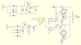
and the schematic for the kit is attached:
I didn't have the voltage regulator they used for the B+ so instead I used a standard circuit of bridge rectifier followed by cap followed by voltage dropping resistor followed by cap followed by voltage dropping resistor followed by cap. This circuit works perfectly in some of my other types of tube headphone amps.
Nobsound 6N5P+6N11 Vacuum Tube Headphone Amplifier Board DIY KIT Single end Class A Amp|Amplifier| - AliExpress
and the schematic for the kit is attached:
I didn't have the voltage regulator they used for the B+ so instead I used a standard circuit of bridge rectifier followed by cap followed by voltage dropping resistor followed by cap followed by voltage dropping resistor followed by cap. This circuit works perfectly in some of my other types of tube headphone amps.
Attachments
so to sum it up, i use the headwaze circuit for the amp itself, the aliexpress circuit for the filament power supply and my own custom B+ supply.
One more note, the circuit diagram for the aliepxress circuit has a 317 voltage regulator, which would not withstand 3-4A current. The kit uses a LT1083 high amp regulator and that is what I am using
I didn't have the voltage regulator they used for the B+ so instead I used a standard circuit of bridge rectifier followed by cap followed by voltage dropping resistor followed by cap followed by voltage dropping resistor followed by cap. This circuit works perfectly in some of my other types of tube headphone amps.
As an experiment, do you have a choke you can use instead of the first voltage dropping resistor?
steventrus: Audacity will let you record audio and then do an FFT on the file. Some software exists for phones but I haven't used any.
Hmm if Q1 is being controlled by an AC rectified input then all that's going to happen is the output is the same rectified output?
I can see a LPF as LC1 and RC1 with 21uF.. but I'm not sure that would really provide much ripple control.
I'm not an expert but that seems missing something.
I can see a LPF as LC1 and RC1 with 21uF.. but I'm not sure that would really provide much ripple control.
I'm not an expert but that seems missing something.
so far I have some input that I will try.
1) pull out the 6v transformer and move it away from the amp board
2) separate the ground on the filament power supply and connect it indirectly to ground through resistor / capacitor.
Thanks for the suggestions and if you can think of any other ideas please let me know
1) pull out the 6v transformer and move it away from the amp board
2) separate the ground on the filament power supply and connect it indirectly to ground through resistor / capacitor.
Thanks for the suggestions and if you can think of any other ideas please let me know
Did you measure the heater supply voltage and the voltage across the 10000uF? The first stage is investigation.
PROBLEM SOLVED !!!!!!!!!!!!
Thanks for all the suggestions. Based on your input this is what I did. I took the complete filament circuit and separated it from the amplifier circuit so that it is only connected to the amplifier ground in one place. Before I had the filament circuit connected to the amplifier ground at several places. For some reason the hum completely disappeared. This is beyond my knowledge of electronics to understand why that fixed the problem, but I am happy that it is fixed and I have learned an important lesson.
Thanks for all the suggestions. Based on your input this is what I did. I took the complete filament circuit and separated it from the amplifier circuit so that it is only connected to the amplifier ground in one place. Before I had the filament circuit connected to the amplifier ground at several places. For some reason the hum completely disappeared. This is beyond my knowledge of electronics to understand why that fixed the problem, but I am happy that it is fixed and I have learned an important lesson.
Good job!
That must mean you had some serious return currents passing a sensitive part of the circuit (the input/gain stage). When only having a single GND connection, the currents are forced to go in the heater wiring, and not find an easier lower impedance path which can also be near something sensitive.
That must mean you had some serious return currents passing a sensitive part of the circuit (the input/gain stage). When only having a single GND connection, the currents are forced to go in the heater wiring, and not find an easier lower impedance path which can also be near something sensitive.
Thanks, and by the way, in my opinion, this 6AS7 headphone amp sounds fantastic. I am using it with 75 ohm headphones and only need to have the volume up about 25% to have a strong output.
This is the third type of headphone amp I have built. The first one was based on the Lehmann design (solid state). While it works fine, i don't care for solid state sound.
The second one I built is based on a white cathode follower design (Morgan Jones) using 3 6922 tubes. It sounds much better than then Lehmann one (in my opinion), but I believe this third one sounds the best.
- Home
- Amplifiers
- Tubes / Valves
- How to get rid of hum in a 6AS7 Headphone Amp