
Butch discovered that the square pads are inconsistent between the MJE340 and MJE350
The square pad on MJE350 is correct, the MJE340 is wrong. I pointed this out in some earlier threads, these boards are a revision from "Jayfree" design. Use the silkscreen for orientation, do not pay attention to the square pad. The footprint files in EasyEda are open source and inconsistent, it was easier to add the silkscreen in lieu of revising the board.
See screenshot of the boards below pointing out a couple of the MJE340 oriented wrong
Attachments
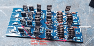
Yes this was very frustrating as the amplifer was acting very strange and very inconsistent voltages all over it. I was chasing my tail for a while the whole time talking to deafbykhorns and he is awsome. I wasnt here for the earlier posts but I could have easily skipped over him mentioning that as I read through the thread ( multiple boards mentioned). We had a lengthy conversation about my issues and I truly didnt think it was the boards but he went way above and beyond to offer help and advice (in my book that speaks volumes). Anyhow I confirmed the pinout a couple hours ago with him and he said to disregard the square pad and I knew right then that was my issue. I basically installed half the transistors backwards. He then told me there is a heavy line on the the board on the side of the would be transistor heat sink side. So I pulled the half of them and reoriented them and the amp functions perfectly. The amp has about + or - 4mv offset and is warming the room up as I type. I'm excited to get a good listen. So when you insert the transistors all of the heatsink sides point toward the heavy line on the board below them. Hats off to deafbykhorns for getting these boards out there and working. He will save many of these amps from becoming boat anchors.
There’s been some discussion about producing these boards in Qty. using SMDs.
If someone can find substitutes for the 2SK70 and 2SJ74 in an SMD device as well as the MJE devices and will do the sims or math, I’ll design the board.
If someone can find substitutes for the 2SK70 and 2SJ74 in an SMD device as well as the MJE devices and will do the sims or math, I’ll design the board.
LSK170 and LSJ74 from LinearSystems.There’s been some discussion about producing these boards in Qty. using SMDs.
If someone can find substitutes for the 2SK70 and 2SJ74 in an SMD device as well as the MJE devices and will do the sims or math, I’ll design the board.
Has anyone determined how the servo works in the D-110? Shouldn't there be a 100k resistor from the output of U1, U2 to the non-inverting inputs of AM1L and AM1R?
Attachments
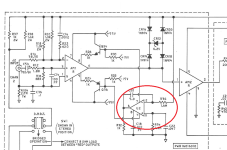
The opamp sources current into R32 which will pull/push the DC offset on the output node to zero.Has anyone determined how the servo works in the D-110? Shouldn't there be a 100k resistor from the output of U1, U2 to the non-inverting inputs of AM1L and AM1R?
Linear Systems JFETS in SMD through DigiKey: https://www.digikey.com/en/products...JHjCAWimIFUPgFdVJSOU1MJIM3ORoseQo-LUVBSuYmJAA
i have a D110b witch i do enjoy,super powerful amp,just picked up a D110 and am going to upgrade it to a D110b specs.
goal is to monoblock them! i do have a slight hum in both units,, i seen the posts from Deathbykhorns,im excited that theres is going to be AM-1 and AM-2
boards available, i cant contact him because i just joined, geuss it will take some time to be cleared for that, realy happy to see
people keeping these amps alive!
Deafbykhorns, Would you also send me 2 of each MA1 and AM2 boards? my email is seeburg148@charter.net
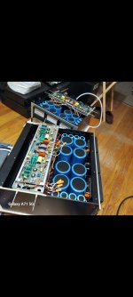
Check this out, my two D110b. Full resto, replaced all Caps,resistors,diodes,LED lights,power cords,disassembled fans and lubed, and replaced all transistors and OPamps, didn't replace all output transistors.
As you can see all the AM 1&2 moduals are new thanks to John-Deafbykhorns!
Took me a total of 6 months to do! And a bucket of money! Last night was the first test run! As you see them in the pic.
Mono blocked them, preamp Audio Research SP-9 and ran them through Klipch Cornwall ones! Absolutely stunning sound! Well worth the time and money!
Couldn't have done it without johns
Analog moduals !
Attachments
I’m out of the country until the 6thDeafbykhorns, Would you also send me 2 of each MA1 and AM2 boards? my email is seeburg148@charter.net
Currently out of boards
Hello deafbykhorns. I'd like to build these modules to repair my d100b amp. I sent you a pm earlier but I forgot to include my email, so if you can pm me I'll respond with that info. If you have more pc boards I'd like to buy what it'd take to replace both modules; otherwise, if you can send me links to the gerber files and bom (as well as who you had do the boards) I can take care of the rest...Again, thank you so much for sharing this info!!!!
Hi Dyni, can you tell me what part you used for the 30000uf and 1900uf caps? I think I've found them but I'd like to use what you found as it fits perfectly. Thanks.Check this out, my two D110b. Full resto, replaced all Caps,resistors,diodes,LED lights,power cords,disassembled fans and lubed, and replaced all transistors and OPamps, didn't replace all output transistors.
As you can see all the AM 1&2 moduals are new thanks to John-Deafbykhorns!
Took me a total of 6 months to do! And a bucket of money! Last night was the first test run! As you see them in the pic.
Mono blocked them, preamp Audio Research SP-9 and ran them through Klipch Cornwall ones! Absolutely stunning sound! Well worth the time and money!
Couldn't have done it without johns
Analog moduals !
Guys are the AM1 and AM2 the same for D100B, 110B? The was chatting with deafbykhorns about boards if I need them, has anyone tested these modules on the circuit board to see if they are ok? Do you only need +15,-15v to test them? I see from the schematic of the D100B, the AM2 requires +50 and -50v to test? Another fellow on another post mentioned you only need 15 volts? That would test the AM1, but not the AM2 correct?
I think you can test it by putting +15 on AM1 Pin8 and -15 on AM Pin5, then apply a test single (e.g., low amplitude sine wave input) signal into pin3 on AM1. That should drive AM2 enough that you could see the output on AM2 pin2 -- There won't be any signal gains with this method, but if it works you should at least see the signal on the output of AM2...I can't guarantee this will work, but it seems to be what that builder you mentioned probably did.
Note: Looking at the circuit again, you may be able to skate with only +15 on AM1 Pin8; just to test the path you probably don't need the differential inputs to AM1.
Just my 2-cents, and my opinion is worth what you paid for it.
Note: Looking at the circuit again, you may be able to skate with only +15 on AM1 Pin8; just to test the path you probably don't need the differential inputs to AM1.
Just my 2-cents, and my opinion is worth what you paid for it.
Last edited:
Ok, thanks for the reply...wish I had an external PS. I may hook up leads to the original supply to whole board, this way I can test and make sure I am also getting the 55v. Original PS works ok, brought it up slowly 10 volts at a time..caps all test good. I have a few blown TO-3 in the right O/P module so wanted to check rest of amp out first before spending $$ on outputs..thanks again...
Your plan sounds reasonable...There are only a handful of electrolytics that should be replaced for the D100B, mostly the 2 on the main board and the 4 on the output board. The ones I had an issue with were the big filter caps and the 1900uf ones in the tracking reg circuit: The issue with these is a) they're darn expensive and b) the originals had low profile screw tops but all the new ones I could find had high profile screw tops, and the high profile screw caps have issues with clearances on the mounting points...Not big issues but I had to make some delrin ring spacers on my lathe so I could use the original mounting system. Also, there's not much wiggle room when choosing the big cap lengths so you have to be careful to be sure your caps aren't longer than the originals -- Shorter is ok but significantly longer will be a real issue.
- Home
- Amplifiers
- Solid State
- How to fix the Audio Research D-110 modules