.....explanation of the curves.....
And that answered what I was trying to figure out as well 😎
I was curious if that was in fact how the point was chosen or not. We already know that correlation does not imply causation. I've always heard that sometimes the best way to get the most accurate answer is to not ask a question but propose the wrong answer 😀Vg1k = -8.5V is not arbitrarily chosen. It's the bias value that we need in order to achieve Ia=46mA and Ig2=2.2mA. These current values are the result of determining the target Pdiss for the plate.. With Vak=200V and Ia=46mA, Pdiss-plate would be 9.2W which is below the maximum rating of 10W. We also can check the Pdiss of the screen (which needs to be kept within the max rating as well). This would be 125V * 2.2mA = 275mW. Well below the max screen dissipation of 1.25W.
shhhhhh don't say his name two more times....he's like beetlejuice and just pops out of nowhere.....tubelab.......

I've talked with him a bit on some circuit topology stuff and am very much aware of his franken-experiments. As scotty said "IM GIVEN 'ER ALL SHE'S GOT CAP'N"
Shush you 😛 I was talking from a *theoretical* standpoint since as you so pointed out, we've only got Vg2 = 110 curves. If we assume (I'll be the a$$ in the assume this time) that they don't change *that much* I was curious what the repercussions were for choosing a 4k load vs a 2k load and what it meant for the design. Aka you can run fixed bias and have loads more clean headroom with 2K Zo but you'll have less power output vs sacrificing some headroom with a 4k Zo that auto-biases to gain some power output.Are you talking about drawing the loadline for the right column? If so, i am wondering how you can do it because the plate characteristics in only for Vg2=110V, not for Vg2=125V as indicated on the right column 😀. However, increasing Vg2 from 110V to 125V would increase the gap between the Vg1k curves. This means Vg1k=0V will be higher. This would imply, yes you will have even less headroom if you choose 4K than 2K.
Also as an exercise, Since we've only got curves for a screen voltage of 110V, could I not use a screen resistor to drop the voltage to 110V (instead of 125) and use the curve to plot out a 200V B+ ? I realize that further lowering the screen voltage will cause it to distort sooner....again I'm just talking *in practice* here.
Here is a handy tool to help you learn, even though it is mostly triodes. Don't make the load line business harder than it really is...
I've come across that. Point remains that it doesn't explain HOW to draw load lines. I'll use a tool when I understand what its doing. Otherwise you're just a monkey pushing buttons.
Of course I'm trying to do all of this while waiting on some different books that I'm sure will cover it all.....I'm just being impatient 🙄
Last edited:
A load line is nothing more than a graphical representation of RL = E/I, by playing with the Triode Calculator for a few minutes, you should be able to make out how the different parameters on the screen are tied together, at least the basic ones... While you are waiting for your books, search for Norman Crowhurst's Basic Audio articles online, he covered the subject well.I've come across that. Point remains that it doesn't explain HOW to draw load lines.
Hey guys, it's 2020 and i just stumbled across this thread.
I'm facing a similar confusion.
I get that when plotting load lines I'm supposed to use V(B)+ on the bottom.
But in Bias current calculators i'm asked to provide Plate-to-Cathode voltage..
Now, on my amp, B+ is 332V but my plate voltage at idle is 321v due to the drop of the OPT's DCR.
It seems on some sites that despite asking for "plate voltage" they're expecting B+ all the same... I'm pulling my hair out over this.
Last edited:
It depends.
You need plate-to-cathode voltage to calculate bias parameters.
But maybe some calculators can take OPT's DCR into account too, and hence they ask for B+: the voltage drop on OPT depends on the quiescent current, so the plate-to-cathode voltage will be different too.
You need plate-to-cathode voltage to calculate bias parameters.
But maybe some calculators can take OPT's DCR into account too, and hence they ask for B+: the voltage drop on OPT depends on the quiescent current, so the plate-to-cathode voltage will be different too.
It depends.
You need plate-to-cathode voltage to calculate bias parameters.
Bingo. @tubby23 maybe this will help:
B+ = plate-to-ground
B+ = plate-to-cathode + cathode-to-ground
Vgk (grid-to-cathode) = -cathode-to-ground
Bingo. @tubby23 maybe this will help:
B+ = plate-to-ground
B+ = plate-to-cathode + cathode-to-ground
So, which is it? ��
Edit... Oh....
So B+ isn't the rail, but the voltage after the OPT?
Last edited:
Also, whilst on the subject, I understand why stock cathode biasing is cold and only about 50% of max plate dissipation - I believe it's because of our weedy 6w OPTs.
I'll be placing an order for 15w, 6.6k units soon and I intend on warming up the power tubes. I've read on a few sites that single ended cathode biased amps can be run at 100%, but these are guitar guys...
What's the crack with hifi?
What's the aim besides more power?
Brighter/clearer Vs less distortion, etc?
The term B+ comes from the days when batteries were more commonly the voltage source. 'B' stands for Battery and + is the positive terminal. The term remained in use even as line voltage power sources became the norm and voltages increased. So now, in tube based electronics the B+ is the voltage across the output of the high voltage supply. It is a supply voltage and is no sure indicator of the voltage on the anode , or what that across the tube will be. It's a supply voltage, how the supply is used determines the rest.
Nope.B+ = plate-to-ground
B+ is PSU voltage (the term is derived from "Battery +"), high voltage output to ground.
B+ = OPT voltage drop + V(plate-to-cathode) + V(cathode-to-ground)
The last component is zero if the bias is fixed (might be a few millivolts if you have current sensing resistor, can be omitted anyway)
Nope.
B+ is PSU voltage (the term is derived from "Battery +"), high voltage output to ground.
B+ = OPT voltage drop + V(plate-to-cathode) + V(cathode-to-ground)
The last component is zero if the bias is fixed (might be a few millivolts if you have current sensing resistor, can be omitted anyway)
Yes i understand that there's an additional OPT drop since it's not a purely reactive load. I should have been clearer for the sticklers too that my example was for a cathode-bias. At the time I had written the reply, it seemed evident since OP was asking about bias current and was confused about the "plate to cathode" voltage and how that related to his "high voltage".
Point being when you set-out to draw the load-lines usually going "my B+/HT/HV/rail/V1+/whatever is x-volts, i start here" is sufficient enough.
So, which is it? ��
Edit... Oh....
So B+ isn't the rail, but the voltage after the OPT?
You can call it whatever you want, but as @hearinspace pointed out there's history there. If you ever see "high tension" or "HT" that's from the days of yore as well and means basically the same thing.
I've seen "Va +", "B+", "HT", "V1/V2/V3" (1,2,3 denoting whatever valve its for) and I'm sure a few others. It's all contextual but in the most general sense it usually means "this is my high voltage".
...and if you are asking youself why they are called B+ and C-, this is the answer:
Battery (vacuum tube - Wikipedia)
Battery (vacuum tube - Wikipedia)
Nope.
B+ is PSU voltage (the term is derived from "Battery +"), high voltage output to ground.
B+ = OPT voltage drop + V(plate-to-cathode) + V(cathode-to-ground)
The last component is zero if the bias is fixed (might be a few millivolts if you have current sensing resistor, can be omitted anyway)
So B+ is the rail and Plate voltage is (B+)-(OPT DCR drop)?
Plotting a load line on a graph or doing calculations for an OP stage is only a start and doesn't really tell you much, it's easier to build the OP stage and experiment. Also a load line for an OP stage is for a fixed secondary load, with a speaker load the lines aren't straight, see - TTT309 Why Tube Amps Sound Different Pt2 - YouTube
For a basic how to see - The Valve Wizard -Single Ended and the PP also. To confuse the situation even more we call B+ HT in the UK, but really there's only a few things you need to know for an OP stage, all these can usually be found on a valves datasheet - primary load, HT, cathode resistor value (or Ik in fixed bias), that's it, the rest you can sort out when you build the prototype.
Andy.
You can call it whatever you want, but as @hearinspace pointed out there's history there. If you ever see "high tension" or "HT" that's from the days of yore as well and means basically the same thing.
I've seen "Va +", "B+", "HT", "V1/V2/V3" (1,2,3 denoting whatever valve its for) and I'm sure a few others. It's all contextual but in the most general sense it usually means "this is my high voltage".
HT high tension
HP high potential (both British uses)
B+ (Us Use, same as above)
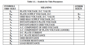
Va, Ea anode volts (British use)
Vp, Ep plate volts (US use, again the same thing as each other but NOT the same as HT/HP or B+)
Last edited:
- Home
- Amplifiers
- Tubes / Valves
- How To Draw Load Line With Output Transformer ?