Although I have not used the Scarlett, most USB interfaces like to be run under -6dBFS for best performance. -8dB is often a good spot. By going back and both testing levels between output and input, you should be able to figure out optimum settings for the output and input levels.
Basically, don't max out the card, bec aue distortions goes up when you do.
Basically, don't max out the card, bec aue distortions goes up when you do.
Yes I get that, and I'm actually not maxing the card (Scarlett 2i2 input at minimum, output 2/3 and REW gen at 0dbFS). But as far as THD is not the bottleneck, if I want to get the best SINAD/ THD+N measurement I need to measure closest possible to 0 dbFS so the noise to signal ratio is lowest possible, am I correct ?
Oui, c'est ca. With a bit of testing you can figure out what "closest possible" is.
FOr me that has been -6dB to -8dB. What you find will depend on your hardware.
FOr me that has been -6dB to -8dB. What you find will depend on your hardware.
So here below is same card now fed by RME ADI2 DAC, best THD+N I can get. Given the specs of the DAC, am I also correct thinking a 98.5db SINAD is the very best I can get from the ADC of my card ? (and that I will never be able to get better results for any Amp measurement I will perform with that card)
Attachments
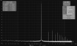
-98 average noise is about what I generally see. Tho you are very close to 0dB, so you might back it down a bit to see if input overload is part of the distortion.
ARTA in spectrum mode will give an RMS value of the signal that seems in line with what REW reports.
ARTA in spectrum mode will give an RMS value of the signal that seems in line with what REW reports.
Ive tried backing down but that didn't improve SINAD.
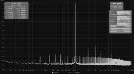
Ok so now I have soldered my Amp voltage divisor to an XLR to use Focusrite's MIC balanced input instead of Line input. As per specs MIC input has slightly better THD+N perfomances.
How is that possible the measured THD is now worse than before ? 😱
Measurements are in the exact same conditions : Amp at 5w output. Only difference is card's MIC input and gain backed off to minimum, so that the Focusrite ADC should be at its best comfort zone. I'm puzzled.
First is line input, second is MIC input.
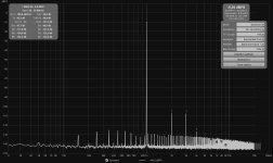
Attachments
Does it ? Now compared to a slight input gain increase to match 0 dbFS, same as it was for Line input measurement. I would say MIC figures (both THD and N) looks much worse, isn't it ?
First is Line, Second is MIC.
I must have done something wrong. Should pin 1 of the XLR be connected to cold as I did ?
First is Line, Second is MIC.
I must have done something wrong. Should pin 1 of the XLR be connected to cold as I did ?
Attachments

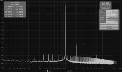
I see 2nd harmonic come up a little on the mic input.
Pin 1 is shield. I would not connect it permanently, but have it wired to an alligator clip that you can connect or disconnect to the device under test. Use whatever gives you the lowest noise. Your amp's negative output post is almost certainly already tied to the common.
Pin 1 is shield. I would not connect it permanently, but have it wired to an alligator clip that you can connect or disconnect to the device under test. Use whatever gives you the lowest noise. Your amp's negative output post is almost certainly already tied to the common.
I don't know if you can do this in REW, but in ARTA you can see the difference between the current measurement and the Overlay (previously saved). In a way that cancels out the harmonics of your measurement rig.
"Class D amplifiers can't be tested directly" -Schmilblick
Должно быть, я сделал что-то не так.
Howto - Distortion Measurements with REW
2x Hypex NC250MP, won't that work ? strange as I previously did tons of measurements which seemed consistent (until the change of card input today...)
Class-D. The RF carrier left on the output could be playing havoc with the input of your soundcard. Usually the RFI is the same on both positive and negative sides, so at least there isn't a large difference between the channels if working in balanced mose. But even common RF on the inputs could be causing you trouble.
It will work, but it is better to put a filter on the ADC input at the PWM frequency, and deal with the ground loops of power sources.Schmilblick
2x Hypex NC250MP, разве это не сработает ?
Howto - Distortion Measurements with REW
Doesn't that also mean that you must measure class D in bal mode? If you do it in se mode you ground one output, which, apart from screwing up your measurement, may not be good for the amp.
Jan
Jan
He should be able to build the voltage divider as balanced. For sure that would be best with a BTL topography.
Hmmm, right, high switching frequency at the output, thanks for bringing that out...
To bad I can't measure that switching noise. At least that would explain why I get better results on MIC input with both loopback and RME but worst with Amp + voltage divisor.
My voltage divisor is fully balanced, I can set pin 1 reference to whatever I choose, exactly as you described Pano. Trust me there is no better result here than biting negative Amp output. Connecting to Amp ground (class1, earthed) is a noise festival, arround -85db.
Amp is the only one earthed, measurement chain is : ShieldTV playing REW's 1khz wav signal (resampled to 192Khz thanks to Android...) to RME ADI2 DAC balanced to double Ncores.
You'll need an oscilloscope or spectrum analyzer for the RF. On some Class-D amps I've seen significant noise up to 10MHz, even tho the switching frequency was near 800kHz. The Hypex is probably cleaner than that.
So should I try to add a capacitor in parallel somewhere, on the divisor, 1uF or lower I guess. I need to read about what I can do about it.
Switching frequency is between 80 and 120 Khz as per specs.
Switching frequency is between 80 and 120 Khz as per specs.
Last edited:
- Home
- Design & Build
- Software Tools
- How to - Distortion Measurements with REW