Hi Everyone, the EML 30A has arrived. I am trying to figure out the load lines, etc. See attached. Please keep me honest on my thinking:
1. Ua = 271V. (I can go with more voltage, but lets use 271V for now).
2. Bias = -2V. (this will support 4Vpp input from my elmaformer. Note: on a daily basis, I listen to about 2.5Vpp. When Zeppelin/Alice/Floyd are on display, 5.2Vpp from the Elmaformer)
3. So, 0V to 4V swing gives us about 120V output swing to drive the GM70. The GM70 is biased at 115V, so in theory operating point should drive the GM70 to full output.
4. Ia = 9mA which is a hair above the 8mA IT spec. I would bet that 9mA won't be a problem. I have emailed Yves at Monolith, but no response to date.
Thoughts?
Attachments
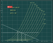
What is the line going from 20 ma on the Y-axis to 500 V on the x-axis ?
I suggest you up the anode to cathode voltage thereby moving the vg1 voltage more negative. This will give you more headroom.
I suggest you up the anode to cathode voltage thereby moving the vg1 voltage more negative. This will give you more headroom.

A couple of items:
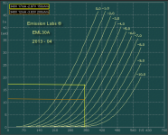
1. The GM70 is biased at 67.5, so I need 115Vpp, Rk=1K
2. EML 30A is installed. Ua = 340V, -2.9V bias, 17mA (too much), Rk=150ohm cathode bias (un-bypassed). This is represented on the attached curve chart in Yellow. The Orange line is hypothetical if Rk=200. I might use Rk=200 to bring down the current to 12mA. Maybe even 250ohm to get near 8mA.
Now I will start listening and then report back. If anyone has other operating points to consider, please share. I can increase the 30A driver Ua up to about 370 if so desired. Not sure its necessary.
Attachments
Pat, unbypassed Rk will rob the 30A of its high performance.
gm will drop to <3mA/V, for Rk of 150 Ohm, and rp will increase, meaning weaker drive to the IT.
Filament bias is an option, if you want to avoid the bypass capacitor.
High Ua is best. 400 - 430V, in order to get a big bias voltage: headroom is needed around the DAC output.
Also, Unbypassed Rk greater than about 60 Ohm (220 - 240V mains supply) or 120 Ohm (110 - 125V) will make for increased 50-60Hz noise in the output of any DHT. Depending on the PT structure and hence leakage capacitance.
The noise stems from the leakage capacitance of the PT. No filtering tricks are effective at reducing it; except back to back PTs. The leakage current is common mode, and always goes home to ground through Rk.
Last edited:
Pat,
If you use EML30 with such very low (9mA) anode current (and relatively low anode voltage), the distortion of grid swing -at about 120..140Vpp- will growing at least 1% more vs. higher voltage, higher current (over 300..400V and near 20mA) operation.
This IT not really compatible with beefy drivers, such EML 20/30 type tubes.
Bela - Trying to maximize the 30A performance, would it be better if I adjusted the GM70 operating point to a lower bias (say -50V), thus requiring only 100Vpp swing?
Rod - I added a 100uF bypass cap to the driver Rk. Much better bass which balanced the sound. Less aggressive. Q: If Filament bias is used with a capacitor, does this compromise the bass performance? I don't fully understand why Filament bias precludes the need for a bypass capacitor.
Rod - I added a 100uF bypass cap to the driver Rk. Much better bass which balanced the sound. Less aggressive. Q: If Filament bias is used with a capacitor, does this compromise the bass performance? I don't fully understand why Filament bias precludes the need for a bypass capacitor.
Vega - I upped the voltage to 430@15ma, best I can do for now. I will listen and report back.
When you responded "No", was the referring to the 100Vpp swing or Filament bias question?
When you responded "No", was the referring to the 100Vpp swing or Filament bias question?
a much better working point for the eml30a
as for unbypassed cathode resistor: the ra of the tube increases:
ra'(unbypassed Rk) = ra + (mu + 1)*Rk
But when dc heating a directly heated triode the cathode resistors value is usually quite low, resulting in small changes in ra.
http://vinylsavor.blogspot.com/2012/03/filament-bias-part-1-concept.html
The " No" was my opinion on lowering b+ for gm-70 instead of increasing the current and voltage for eml 30a
Hi everyone, just following up. I tried the EML 30A with several operating points, however, this tube is not my cup of tea. I prefer the older tube sound in my amps so I installed a VT-52 driver. I really enjoy the VT-52 (841), but I know that it is not a good match with my IT. Andy Evans says to try the 10Y as well, so I may give this a go, although the mu is only 8 which I suspect is too low for my needs.
If anyone is interested in a new pair of EML 30A tubes, let me know.
If anyone is interested in a new pair of EML 30A tubes, let me know.
841 military sign is VT-51.
If you want to use 10Y/801a, must to use input setup transformer.
For example 1:4 SUT, R loaded 801a, parafeed 1:1 IT gives 130-140Vpp swing at 2V RMS input.
If you want to use 10Y/801a, must to use input setup transformer.
For example 1:4 SUT, R loaded 801a, parafeed 1:1 IT gives 130-140Vpp swing at 2V RMS input.
I am probably also correct that one should also include the grid/cathode capacitance as to complete the seriousness of the slew problem. This can mount up as I found out using 12HG7´s as triodes. These tubes make excellent drivers, but hey, watch out the effective Miller loading and input c´s on the previous stage !Keep me honest. Here are my calculations:
Assume max frequency = 20K
Voltage swing GM70 = 850V
GM70 plate-to-grid capacitance = 12pF
GM70 gain = 6.7
GM70 miller capacitance = 12pF * (6.7+1) =92.4pF
I = 2 * pi * 20,000 * 900V * 92.4 = 10.4mA
Correct?
Pat, Did you use a different IT to try the EML30A at 400V 20mA (or near to that?).
IME, new EMLs need quite a long period of running-in to properly do justice to the sound they are capable of. They sound somewhat less vivid, until the coatings have reached their equilibrium: the composition at the active surface changes, as the fresh barium rises up from the sub-surface.
IME, new EMLs need quite a long period of running-in to properly do justice to the sound they are capable of. They sound somewhat less vivid, until the coatings have reached their equilibrium: the composition at the active surface changes, as the fresh barium rises up from the sub-surface.
Rod - I only have 1 IT, the nano from Monolith. I am running the EML 30A at 420V, 11mA. The tubes only have about 15 hours on them. Yesterday they started to sound better than 2 weeks ago when I replaced them with the 841. I hear the following (completely subjective):
1. Bass is better with the EML 30A. Why? 30A is a better match with the IT (200H). 30A has Rp=8.5K whereas the 841 Rp=63K. That's a huge difference.
2. 841 has better tone. Probably due to increased 2nd HD. I love the tone of the 841, but the bass is not good due to the IT mismatch.
3. 30A has better clarity, less distortion. However, this comes at the expense of a less pleasing tone which sounds a bit "in your face" and not colorful. It's not harsh, but rather black/white (as you said Rod, less vivid). Hopefully some break-in time will alleviate this.
4. 30A is more quiet, deeper soundstage.
5. most noticeable is the improved dynamics of the 30A. I can play the 30A with lower volume/output and it sounds dynamic. Piano keystrokes are more lifelike with the 30A.
More to come!
This idea of Vegard's - to ask about modifying the IT to accommodate more standing current is worth following up. The 30A will offer a lot more with optimised setup (more voltage AND current). The EML is really worth the effort, IMHONo
Up current up voltage aka 400@20 ma
And ask Monolith to change the gap in the it
If the Monolith IT is potted then modifying is not easy.
Even if it is possible, it would be wrong: To double the airgap for 18mA would half the inductance: from 200H to lean 100H. (Impedance ca 12K) That is no good load for the 8.5kOhm EML 30A tube.
Banpuku would need a new IT for 20mA with 200H. (Expensive) An IT for 20mA instead of 9mA means much more windings, higher dcr, interwinding capacitance, less good frequence response. Ask a transformer winder.
His current IT has the wrong technical parameters and can not be adjusted for the EML 30A as optimal load at 18-20mA bias.
banpuku: Give the EML 30A more burn in: 100-150 hours. The sound will become better. But it will not sound like good NOS tubes.
Important: These modern EML tubes need the exact Filament voltage as in datasheet. Read at EML website.
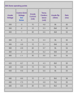
Please see attached snapshot from EMLs site showing a recommended operating point of 420V and 10mA. Someone please explain why 10mA is insufficient and why it would be worth the effort to double the current. Mu is higher with 10mA. Rp is 8.5K vs. 6K with 10mA (compared to 20mA), but not enough to justify a new IT.
Attachments
Pat,
Why not ask Dave Slagle?
I have some -old- Slagle transformers, for example 145H/25mA 1:1 IT, which is good for EML30A too.
BTW I more prefer EML20A(M). Lower gain, but lower impedance too.
Why not ask Dave Slagle?
I have some -old- Slagle transformers, for example 145H/25mA 1:1 IT, which is good for EML30A too.
BTW I more prefer EML20A(M). Lower gain, but lower impedance too.
Partly because a higher anode current places you in the more linear parts of the triode curves, and partly because current is robbed by the capacitance of the power triode, and stray capacitances, and any grid-to ground resistors.please explain why 10mA is insufficient and why it would be worth the effort to double the current.
Since this calculation was the question that opened the thread, someone had better do the arithmetic.
Start with a rough estimate of the capacitances:
20pF for various strays: wiring, IT
Power Triode: ca. 8pF + 150pF
Call it 200pF to round up.
Let's say you want to drive it to full power at f=14kHz (this gives a bit of margin compared to real music), and say the zero-to-peak voltage Û is 100V.
The fastest slew-rate is then 2.π.f.Û = 8.8V/µs.
Peak current [ î ] in the capacitance is in the usual relationship C.V = i.t
so î = 200p*8.8/1µ = 1.8mA
No grid to ground resistor - you have an IT; no extra current is robbed in this case. But this is often a major contributor, with RC coupling, for example.
The 1.8mA is robbed from the EML30 anode current; so if it started at 8mA it drops transiently to 6.2mA - you can see the potential for high frequency distortion.
You might be able to get away with Ia=10mA of you have a FET source follower. A really well implemented one might get the overall capacitance below 30pF.
The IT would need to be truly rated for 10mA, though: if it is not, the inductance falls, and saturation effects would be worse than the thin current's effects.
- Home
- Amplifiers
- Tubes / Valves
- How to determine current requirements for output tube from the driver