Hello Pat,
I think this can be starting point.
As additional gain stage is necessary, you can use it for additional 6dB roll-of, just as Thorsten did. If you tune -3dB point of that roll-of at 45-50kHz (which leads to some -0.7dB at 20KHz), then R1 should be 50ohms.
Pedja
I think this can be starting point.
As additional gain stage is necessary, you can use it for additional 6dB roll-of, just as Thorsten did. If you tune -3dB point of that roll-of at 45-50kHz (which leads to some -0.7dB at 20KHz), then R1 should be 50ohms.
Pedja
Attachments

Hi Pedja,
I heard that voltage compliance of the 1541 is only 25mV. A 50 ohm resistor there with 2mA current output will swing 100mV already.
I think your I/V resistor is too high a value. 10 ohm shoudl be more like it. Anyone?
DonJuan
I heard that voltage compliance of the 1541 is only 25mV. A 50 ohm resistor there with 2mA current output will swing 100mV already.
I think your I/V resistor is too high a value. 10 ohm shoudl be more like it. Anyone?
DonJuan
Thanks
I am trying that out with switchcad,.
I also received some help and suggestion from yeo at diyparadise.com and he used different values.
I will try both and tweak around a bit and hopefully can post something meaningful soon.
thanks again.
I am trying that out with switchcad,.
I also received some help and suggestion from yeo at diyparadise.com and he used different values.
I will try both and tweak around a bit and hopefully can post something meaningful soon.
thanks again.
Hi Patwen,
How are things going with your TDA1541 I/V resistor... I've used 100Ohm last weekend but is didn't sound good.. and worse ( 😉 ) it looked very noise on the scope with lots of HF artefacts.. my TDA1543 (also build last weekend) sounded better and more importand: it looked better on scope too 😀
I decided to go active for the I/V conversion. I am using an ultra simple BJT ( 3 resistor, 1 diode, 1 NPN) stage and I like it better than the 100Ohm passive way.
Goodluck,
Thijs
probably diodes are the key. i can remind me that we used them in school for generating a sine wave from a triangular source. What I know is that the transfer characteristic from of the diode creates a wonderful sine with 0,xxx% THD. I´ll loo for a schematic for deeper investigation.
don´t kill me if I`m totaly wrong with this....
don´t kill me if I`m totaly wrong with this....
Dear patwen,
lit look like so, that i am today on the same situation, who you are been in Januar--i think built one good DAC and may be with TDA1541 and may be 2 parallel ships project. Who are you now and are you doing the dac and what you can say me.
thanks
hifiwolf
lit look like so, that i am today on the same situation, who you are been in Januar--i think built one good DAC and may be with TDA1541 and may be 2 parallel ships project. Who are you now and are you doing the dac and what you can say me.
thanks
hifiwolf
patwen said:hi,
I am planning to built a non-oversampling DAC based on TDA1541A.
Would someone kindly point me to some place where I can learn how to built a sinx/x filter to compensate the non-oversampling's roll off?
Thanks
Pat
filter built ....
Thanks, with the help of the good people here, I have built the sin(x)/x filter using switchcad.
I will post the filter circuit here once I get back to my house. The filter is very simple (T's one is better as he dealt with the digital images) and used the parts I used for the digital antidote project.
Before adding the circuit, the sound of the NOS TDA1541A is nice, but dark and roll out at HF, after a while is become boring and lifeless.
Once the filter is added, the DAC sound much more alive, natural, and the shorting comings of "dark soundsing", "roll off" and "loss of detail" is gone.
Now it sound like the latest 24bit/96KHz DAC BUT with the body and warmth of the TDA1541A, just great.
IMHO, this is an essential additional for all the NOS DAC (no just the TDA1541A) out there, as the sin(x)/x roll offf is quite noticable if not dealt with.
sin(x)/x compensation filter
This is the sin(x)/x compensation filter which I am currently using. I tried to make it as simiple as possible and use standard values (and parts left over from my previous projects).
😀
 this filter is tuned for CD with a 100ohm output impedance.
This is the sin(x)/x compensation filter which I am currently using. I tried to make it as simiple as possible and use standard values (and parts left over from my previous projects).
😀
this filter is tuned for CD with a 100ohm output impedance.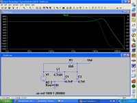
Patwen?
You should try 15 Ohm instead fo 100 Ohm.
Can you post schematic with new values for the 15 Ohm version?🙂
You should try 15 Ohm instead fo 100 Ohm.
Can you post schematic with new values for the 15 Ohm version?🙂
bad result
I made a try and have built the Patwen's sinx/x filter in the next
environment: tda1541 Dac chip, Jocko's I/V converter( Rbroer version), Patwen's sinx/x filter, differential balanced tube buffer.
No measuring, only by ear:
Without the filter the DAC is flying, wide stage , great bass and highs, details.. etc.
With filter everything get a shadow, the state is similar when there was no DAC (this is my first DAC project).
Jocko, Rbroer
what is the output inpedance of the I/V converter?
Patwen
what are your impressions about the effect of the filter?
George
What components did you use?
Hi,
The Sin(x)/x filter was design with near "perfect" components. Especially the caps, you have to use the best caps available (I used silver mica), do not use any EL caps, it will change the whole freq response.
Due to the small DC component existed from the TDA1541A (if you connect the filter directly to it), you will also need an inductor that can withstand some DC.
So try that out and see.
From my experience, the filter is a must, without the filter, the highs are dark and roll off, also seems less "details". (only "seems", because the details was there but at a lower vol.)
With the filter, the characteristic of the sound has not been changed, still the NOS sound, but add more life and spakle in the highs and seems to have more "details".
sinx/x filter
Hi Patwen!
I am glad to hear the filter works well in your circuit.
I used quite "normal" components - Wima capacitors, metalfilm
resistor, etc. The filter was in between Jocko's active I/V converter(Rbroer version) and an Jfet input tube buffer.(http://www.diyaudio.com/forums/showthread.php?threadid=9226&highlight=I/V+converter)
I don't know the output impedance of this I/V converter, so I put
a potmeter to the place of 680ohm. As I mentioned the sound
was bad at any resistor value(pot). Later I examined the signal by scope and there was a continous oscillation superimposed on the signal.
So I use my dac without sinx/x filter, but would make further experiments.
George
Re: sinx/x filter
Hi,
You cannot actually do that, you know. Well, or rather, you can do that but it makes zip sense that way and will not work.
You need to include the SINC filter into the load of the I/V converter, namely in series to the resistor in the Anode/Collector/Drain of the device that does the I/V conversion, scaled to suite the impednaces there of course.
Sayonara
Hi,
The filter was in between Jocko's active I/V converter(Rbroer version) and an Jfet input tube buffer.(http://www.diyaudio.com/forums/showthread.php?threadid=9226&highlight=I/V+converter)
You cannot actually do that, you know. Well, or rather, you can do that but it makes zip sense that way and will not work.
You need to include the SINC filter into the load of the I/V converter, namely in series to the resistor in the Anode/Collector/Drain of the device that does the I/V conversion, scaled to suite the impednaces there of course.
Sayonara
Re: Re: sinx/x filter
Hi,
In the referenced schematic in the referenced thread this resistor is 1k5 - R4....
Sayonara
Hi,
You need to include the SINC filter into the load of the I/V converter, namely in series to the resistor in the Anode/Collector/Drain of the device that does the I/V conversion, scaled to suite the impednaces there of course.
In the referenced schematic in the referenced thread this resistor is 1k5 - R4....
Sayonara
sinx/x filter
Hi Kuei!
It is quite logical, sorry I am not qualified in EE, only a DIYer,
but I learn a lot here and there, thanks to you and the other great guys.
My DAC has started from your Adagio, and as you see I made some changes (good or bad ones, who knows ?).
Is there any new project by you in the DAC topic?
Thanks for the help
George
Re: sinx/x filter
Hi,
Not really. But I intend to publish soon a little DIY Article how to fit a non oversampling DAC (TDA1543) to the Marantz CD63/67/6000 series, including a valve output stage and with a "anti-sinc" filter and instead of using a lowpass to wipe out ultrasonic trash using multiple partallel LC series resonance circuits, tuned to 44.1KHz, 88.2KHz, 132.3KHz, 176.4KHz and 220.5KHz respectively.
This will aim at being as simple as possible and as foolproof as possible, with obvious limits to overall sound quality (sorry).
Ciao T
Hi,
Is there any new project by you in the DAC topic?
Not really. But I intend to publish soon a little DIY Article how to fit a non oversampling DAC (TDA1543) to the Marantz CD63/67/6000 series, including a valve output stage and with a "anti-sinc" filter and instead of using a lowpass to wipe out ultrasonic trash using multiple partallel LC series resonance circuits, tuned to 44.1KHz, 88.2KHz, 132.3KHz, 176.4KHz and 220.5KHz respectively.
This will aim at being as simple as possible and as foolproof as possible, with obvious limits to overall sound quality (sorry).
Ciao T
Not really. But I intend to publish soon a little DIY Article how to fit a non oversampling DAC (TDA1543) to the Marantz CD63/67/6000 series, including a valve output stage and with a "anti-sinc" filter and instead of using a lowpass to wipe out ultrasonic trash using multiple partallel LC series resonance circuits, tuned to 44.1KHz, 88.2KHz, 132.3KHz, 176.4KHz and 220.5KHz respectively.
Aha! Thought I already did half the job! http://diyparadise.com/rm20dac.html
For tube output stage, i'm thinking of a common cathode 5842... trying to avoid "too commonly used" 6922s.
I see what you mean by multiple parallel LC series resonance circuit. I did one for 44.1kHz.
DonJuan
- Status
- Not open for further replies.
- Home
- Source & Line
- Digital Source
- how to design sinx/x filter for TDA1541A?