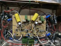
The ripple entering the preamp box is only a few mA. The cascaded filters on the right of the photo must reduce that to negligible levels. The pulses of noise, of frequency perhaps 0.5 Hz, contain a squeal, so definitely oscillation!
Do you have a possibility for quickly trying and change that input cap to 1uF? (or maybe 100nF, just for trying)
I suspect low frequency oscillations (called "motorboating" in the good old days....)
I suspect low frequency oscillations (called "motorboating" in the good old days....)
How much preamp is hung off the "48V" supply? The posted schematic shows a very (op-amp level) high gain, all tied to a single supply with no isolation. We've gotten accustomed to getting away with stuff like this from working with monolythic op-amps designed to include very, very PSRRs that don't apply to homemade discrete component designs. For discrete component designs, either (or preferably both) a high PSRR and/or some supply decoupling are needed.Btw, the problem also shows up on the line stage, at a much lower volume, despite the selector switch removing any electrical connection.
Otherwise, oscillation caused by coupling through the non-zero supply impedance is durned-near guaranteed.
All good fortune,
Chris
the center emitter follower with a big cap from base to gnd looks like a classic colpitts RF oscillator, if there is some stray inductance around it.
Hesener, I can try but the noise which comes in pulses contains a squeal as well as a 100 Hz component
Chris, there are 4 double RC filters, seen on the right of the photo, supplying different stages and channels. The first, highest gain stage, has one of its own, with the second stage and the emitter followers sharing a filter. The voltage entering the box is about 70V stepped down to 48-ish V by the filters.
basreflex, the big cap 680uF is in the bias circuit of the second Sziklai stage so I am not quite sure what you mean, although there will certainly be some stray inductance around with this what I laughingly call my point to point wiring. I don’t know how to make PCBs but I have always gotten away with it previously.
The thing which is really confusing is that it worked perfectly for a week, and only developed the problem when I brought it to my brother’s place. It could be made to stop by holding or even just standing on the umbilical from the main power supply-this must imply HF oscillation!
You are saying it worked and after moving it to another place stopped working properly. Can be soldering of filtering capacitors failed, or capacitors itself? Voltage for such sensitive things like preamplfiers must be very vell regulated, not only filtered. Try to add zeners, may be few in series, somewhere in filter. Resistor from +70v must be reduced in value , to add some current to zener. I would experiment a little, while circuit operating, reduce volume , and add capacitor to gnd , and listen if there are changes. Also, you are saying about pulsed oscillation, that reminds me of mobile phone nearby or wifi router, they working at packet mode, and this is detected by unfiltered circuits ,or unhielded ,unscreened.
The filters were originally zeners but I changed them because I feared that it was the pass transistors that were oscillating. Both configurations produced the identical result. I have also tried with other power supplies, regulated and unregulated, with always the same result.
In London there is a ridiculous amount of high frequency interference everywhere!
In London there is a ridiculous amount of high frequency interference everywhere!
Actually by looking at schematic, i see no global feedback, so it's very strange, how it can oscillate at all. If you have capacitor kinda like 1uf , better film or foil, experiment with it, try to shunt inputs to ground, of variuos stages, and to different grounds. If you have noise at output, this noise must be reaching output stage somehow, maybe coming from previous stage. Also, everywhere with signals, use shielded cable, even if few cm long. For input to phono head it's another question, how to protect it, maybe rf cable with low capacity to shield would help, or 100ohm in series with input and 22-100pf to ground rf filter. Gather more data.
I suspect the output is driving a different capacitive load due to a different cable at your brother's, and that's what makes it oscillate. This may have nothing to do with the Sziklai pairs.Bonsai, The preamp is for my brother and the reason for the input diff pair is that he may replace his tonearm in the near future with one which has twisted pair and overall shield. The inexplicable thing is that everything worked perfectly when I was running the thing for a whole week, but when I brought it to my brother’s place there was immediate loud and continuous noise which is now pulsing in nature rather than continuous and the pulsing is exactly coordinated and identical on both channels. I can’t see anything that would change with time except for the electrolytic caps and cannot see why this change could cause a problem. I know that Sziklai pairs are notorious but I have used them frequently without this difficulty.
Try adding a small resistor in series with the output, maybe 470 ohms.
This may fix it, but both channels with the identical output suggests signals going through the power supply connection and/or ground, as others have mentioned.

A Sziklai pair is a two-stage amplifier with negative feedback. Whenever there is feedback, there must be frequency compensation. Sometimes it occurs "naturally" (or rather coincidentally), as parasitics combine with the change of BJT parameters over frequency. However, leaving this to a chance is inviting stability problems.
Practically speaking, a resistor in the emitter of the first transistor (as suggested by @tombo56 above, Re on the schematic below) adds local feedback in the first stage of the Sziklai pair and thus reduces the loop gain, which may help stability. Another approach is to connect a resistor (10s of ohms) in series with a capacitor (10s or 100s of pF) across the BE junction of the 2nd transistor (Rc Cc):

Practically speaking, a resistor in the emitter of the first transistor (as suggested by @tombo56 above, Re on the schematic below) adds local feedback in the first stage of the Sziklai pair and thus reduces the loop gain, which may help stability. Another approach is to connect a resistor (10s of ohms) in series with a capacitor (10s or 100s of pF) across the BE junction of the 2nd transistor (Rc Cc):
Last edited:
I will do the bypassing first, (easiest!) and then tombo’s suggestion. I’m still pretty convinced that it’s oscillation and that very low level noise from the power supply/ground is riding on that. I have always gotten away with uncompensated Sziklai pairs in the past but bc337 and bc 327 have somewhat higher interelectrode capacitances than those I have used before and perhaps that makes a difference.
All that spaced out point-to-point wiring means a lot more stray inductance than would be normal, that's not going to help - a PCB or stripboard will make the layout a lot tighter and reduce all those loop-areas (aka magnetic antennas).
I've had success with the BC337/327 pair in a CFP and no external compensation, but the currents through each device will play a role as they set the gain of each device. Usually, 2k on the NPN's collector (R1 in the below schematic) puts me in a good place.
I'm a little worried about the point to point build. Do you think you can get the Sziklai pairs' loops a bit tighter? A low pass on the input might not be a bad idea.
I would also consider whether or not the CFPs are bringing much to the party here. The signal levels are low enough that linearity shouldn't be much of an issue, and you have a DC blocking cap such that base current won't matter, either. I'd give some consideration to using a singleton or darlington. If you want to try something fancy SSM2212 matched pair on the input, or even a JFE2140 (with some small tweaks), could avoid the oscillation and might even improve CMRR.
I've had some success with installing Cc, but never thought to install Rc. Looks like a great idea.
I'm a little worried about the point to point build. Do you think you can get the Sziklai pairs' loops a bit tighter? A low pass on the input might not be a bad idea.
I would also consider whether or not the CFPs are bringing much to the party here. The signal levels are low enough that linearity shouldn't be much of an issue, and you have a DC blocking cap such that base current won't matter, either. I'd give some consideration to using a singleton or darlington. If you want to try something fancy SSM2212 matched pair on the input, or even a JFE2140 (with some small tweaks), could avoid the oscillation and might even improve CMRR.
This is my own, same topology, except no line stage, different transistors and much lower current in the high gain stage. No problems whatsoever. I absolutely take the point about the wiring. The problem is, I started with tubes and never learned how to make PCBs. I do have a physics degree but I’m not good with tech stuff.Things like Gerber files or using computer simulations are quite beyond me! Never the less, I have not had this problem until now.
Attachments
A bit less, it's been a while but I think I used 2.5mA per phase, 5mA total tail current? I suspect it's close enough. For reference, I'm using the BC337-40 and BC327-40, and my invoice says they're Onsemi parts purchased before they acquired Fairchild.
I drafted some boards to make prototyping Sziklai differential pairs easier, perhaps they could be of use to you.
https://oshpark.com/shared_projects/V6hmY0R6
I drafted some boards to make prototyping Sziklai differential pairs easier, perhaps they could be of use to you.
https://oshpark.com/shared_projects/V6hmY0R6
Bypassing the non-driven input has stopped the pulsing. The noise is now steady. Curiously, the sound is not distorted, just background noise.
This is a very interesting circuit.
Using input bias resistors and miller capacitance to set a -3dB bandwidth at approx. 5.8 kHz. Have to test this IRL too.
How ever the problem to solve was oscillation, and I played around with a simulation and I might have found the reason for oscillation.
When using this circuit in full bandwidth (right hand bias circuit grounded) I see one pole at 920 kHz and one at approx. 30 MHz and the gain of 37 dB over all will make the 30 Mhz pole have some gain too, and I think that is the possible reason for oscillation.
I put a 47pF capacitor between both 9,1 kOhm output resistors to set the first pole at approx. 150 kHz which will place the second pole at 30 Mhz without gain.
That MIGHT be a solution for not getting the Sziklai pair into oscillation.
First picture shows 1st and 2nd poles.
By reducing bandwidth for the first pole to 150 kHz the second pole are placed below 0 dB gain. Picture 2.
Picture 3 shows gain starting get out of control.
Orange curve output
Green curve input
Purple (Sziklai feedback too slow creating oscillation???)
Picture 4 is result of bandwidth limit of 150 kHz of gain stage.
Purple (Sziklai feedback loop faster than output bandwidth???)
I assume 10dB lower gain would make the circuit stable too, but I believe this is another way to do it.
This is a sort of best guess and I think it's worth to try and see if it fixes the problem of oscillation from the Sziklai pair.
Picture 5 is the frequency range for this circuit which I find very interesting.
I have never thought of using miller capacitanses of a transitor and a high bias circuit for creating a low pass pole like this. Very unique.
I have similar low pass filter at approx. 5-6 kHz in my first stage of phono stages, but do it more traditionally.
But the way it's done here is intriguing.
Last edited:
Wow! Thank you very much for this, flex2. Also thanks to everyone else: I have learned so much about Sziklai pairs, which I am still trying to absorb. There is a dearth of information in the usual textbooks which I have found very frustrating.
Actually flex2, I had not assumed that the miller capacitance was quite so high (again, I have not found a way to calculate it, so I always try to make a reasonable guess). Why do you always try to limit the bandwidth to as low as 5-6 kHz in your phono input stages?
I am now rebuilding the first stage completely having made the decision to reduce the currents by a factor of 4 using bc559/60 and applying compensation as well. I expect the Miller capacitance will be lower, considerably lower.
Last edited:
- Home
- Source & Line
- Analogue Source
- How to damp Sziklai oscillation?