Hello,
I have a pair of monster chokes that I want to use in a symmetrical power supply as drawn at the bottom of the page. In the end it will be a choke input but the way things are connected will be the same ( the first pair of caps will not be there).
I did try the choke in a single power supply with a 3A load no problem.
BUT how to connect them in a symmetrical power supply? Should the wires coming from the first two caps, so the positive and the negative both enter at the start or the finish of the two coils or one at the start and the other one at the finish?
When putting the two coils in series in the wrong way in a choke input in a single rail power supply with choke input the unit will not work as a choke but one would get just a voltage drop because of the dcr of the wire? With a proper load dc voltage will be below ac voltage of the transformer and not properly connect there will be a not so big voltage drop.
Greetings, Eduard
Attachments

Looks like a transformer to me, not a choke. No air gap.
No. It's a common mode choke.
Eduard, you want the currents in the coils to cancel out the DC, just like in the primary of an output transformer. So assuming the winding directions are the same, enter at the start of one and the end of the other. If the winding directions are opposite, reverse that.
They could be common mode inductors to attenuate interference.
I wonder if measuring and posting coil resistances would help an expert guide you to a potential use?
I wonder if measuring and posting coil resistances would help an expert guide you to a potential use?
They are chokes for sure
Hello,
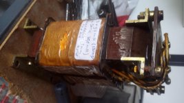
They are telefunken chokes from some decades ago.
If I remember well they did give a considerable voltage drop so I guess they are functioning like a choke. The specs are on one of the photos and you can also see the way they have been used looking at the way the 2 coils are connected.
I also don't see an air gap and I don't think it will be hidden by the two coils. If I do remember well I did do a test with the two coils in series but I wanna use them the way drawn in my first post.
When I did test them in a single rail power supply the temperature rise was very moderate so I think there was no saturation.
Maybe I will take one to Vietnam end of this year to try in a nelson pass class A amp which has a symmetrical power supply. So need to be sure before carrying it on my trip.
Maybe using both coils in series will be OK but using it in a symmetrical power supply will not function.
A pity the company where I bought them knows nothing about their original use so looking for expertise here. Maybe use in clc will work easier than when used in choke input where life can be hard.
Greetings, eduard
Hello,
They are telefunken chokes from some decades ago.
If I remember well they did give a considerable voltage drop so I guess they are functioning like a choke. The specs are on one of the photos and you can also see the way they have been used looking at the way the 2 coils are connected.
I also don't see an air gap and I don't think it will be hidden by the two coils. If I do remember well I did do a test with the two coils in series but I wanna use them the way drawn in my first post.
When I did test them in a single rail power supply the temperature rise was very moderate so I think there was no saturation.
Maybe I will take one to Vietnam end of this year to try in a nelson pass class A amp which has a symmetrical power supply. So need to be sure before carrying it on my trip.
Maybe using both coils in series will be OK but using it in a symmetrical power supply will not function.
A pity the company where I bought them knows nothing about their original use so looking for expertise here. Maybe use in clc will work easier than when used in choke input where life can be hard.
Greetings, eduard
Attachments
clc use requires more of an air gap, hence heavier gauge wire for a given inductance. At the input to the supply you may get away with closed cores, and some resistance isn't always a bad thing in the first loop.Maybe use in clc will work easier than when used in choke input where life can be hard.
Greetings, eduard
Reduce the first capacitance by all means, but don't eliminate it for choke input, even if it's just a small film cap.
Hello,
The other photo of the choke shows that the two coils are interconnected. Both outside windings are connected to each other and then to a terminal. Then the inner windings of the two coils each have their own terminal.
It looks like the '' centertap connection '' has not been used in the original application.
Greetings, Eduard
A common-mode choke is not the same as a pair of smoothing chokes. In a perfectly balanced symmetric supply (i.e. balanced load, as well as balanced PSU) you might be able to use a differential-mode choke, but in an unbalanced supply (e.g. the real world) you need to stop both common-mode and differential-mode ripple so you need two separate chokes.
Two windings on one core make:
- a transformer (which can be considered to be a voltage-mode common-mode choke)
- a choke with two inductance values
- a common-mode choke (i.e. a current-mode common-mode choke)
- a differential-mode choke
- an autotransformer
Two windings on one core never make two chokes! You only get the advantage of current cancellation (so OK with no air gap) when used as a transformer or CM choke.
2 (identical) windings on one core will work as 2 chokes , for a symmetrical supply, but you need an airgap, if you connect the windings that DC magnetization cancels out, the choke-effect cancels out too. I will build a powersupply with 1 choke for + and - and when it is ready I'll give the results.
Last edited:
Hello,
I wanted to use them the way the Lundahl chokes can be used. BUT these have an airgap.
I did ask Per Lundahl about the use of his chokes in this application. He answered:
Regarding the common mode schematic:
The idea with a choke connected in "common-mode block" is that you normally have the same current in both coils. As there are bypasses (through ground) you must make sure that both sides are loaded equally.
If you do, yes LL2733/LL1694 should work.
If i would make up a test set up with a symmetrical power supply with an equal load for the + and the - side it will only work for the lundahl chokes i presume but not for my telefunkens.
What if you use the telefunken in a non symmetrical topology. One coil in plus and the other one in the return?
Wanna find an application for the Telefunken because they have high mH and low DCR
Greetings, Eduard
It seems like you don't actually have a particular application, or have you tested them to identify how the inductance varies with the level of un-balanced DC current, or do you know the test method used to provide the labelled inductance (.ie. what the excitation voltage was), or the self-resonant frequency of each coil?
Using a part in a circuit is most beneficial when you know what the part can do, and you know (by design or simulation) what it will achieve to the final circuit performance.
Using a part in a circuit is most beneficial when you know what the part can do, and you know (by design or simulation) what it will achieve to the final circuit performance.
Hello,
I only know the inductance at 120 hertz that was given to me by the seller. This is indicated on a sticker in one of the photos.
Because they were not expensive i did buy them and wanted to try them in the DDDAC power supply. Later i thoughjt about using them in a Nelson Pass class A power amp.
I did use my first choke in Hiraga le classe A in the eighties.
There are not a lot of high current chokes on the market with 100mH. So far did use Hammonds and Lundahl and i prefer the Lundahls. If the Telefunken wont work i will go for Lundahl. They are nice and here the price is ok.
Greetings Eduard
Eduard, inductance value varies by a substantial amount depending on the applied AC voltage, and in your coupled inductor's case by the differential DC current level.
If you are keen then you can measure those values, as they are the fundamental information needed if you then want to design them in to a power supply.
If you have no need to appreciate the performance that can be achieved, then the details you have so far will no doubt suit.
http://dalmura.com.au/projects/Choke%20measurement.pdf
Ciao, Tim
Hello Tim,
I did come across similar information to the info you have been given. Chokes having the same mH rating under different loads. Some applications that could be nice in others maybe not so benificial.
If i want chokes that will work properly i better use the Lundahls. If i want to use the telefunken or take them to a friend in Vietnam i better be sure before packing.
So far i only did try the telefunken with both coils in series in a choke input test and there was the kind of voltage drop that you would expect in choke input. If replacing the choke by a big big power resistor and voltage drop is way lower isnt that a sign that the choke is working? But one doesnt know how well of course.
Greetings, Eduard
Use this choke(s)
Dear Eduard,
there´s a way to use these choke(s) effectively in a symmetrical supply. We (me and some friends) had done it, cutting the core carefully into halves at the middle point.
There´s always some space between coils (and coil formers), so we cutted so that the rest of the laminated iron was enough to place a new packet of new laminations there, lying nearly by / parallel to the coil former.
We used a vice to clamp the old laminations tightly together with the new ones, and two thicker sheets at the sides. Then we drilled 4 holes (for steel screws, naturally) per new choke, to fix the new i core to the old (now) u (or c) cores.
Cause the cut itself, and its angle, is seldom "perfect" (exactly 90° and absolutely smooth), an air gap (on both sides) is generated. You can also lengthen the outer holes on the (four per choke) sheets, to be able to adjust it. So we did, with good results.
Idea: Another possibility was, to put the new laminations 90° turned on, and fix/clamp it again tightly into a heavy vice.
(But, because one has seldom access to i-core laminations of the right width, that would be exactly the depth of the old core, one has to take something, that only roughly fits there, you would better use some softwood between vice and iron, to get the necessary force onto it all, or some sheets, to get a fit.)
Now you can drill through the i-core in the "right" direction, and through the old core in the "false", one would say... cause the resulting hole would not be vertical to the flat lamination... but listen to the advantages, before you damn it all:
1. You only have to drill 2 holes (ok, therefore you´ll need much longer screws).
2. You have not only the possibility, to adjust a gap between i and u (like above), instead you can use two half i cores (or cut one into halves), and let it touch the old u as much as you want (if), and use one new air gap - between i-core halves. (Still not the "yellow of the egg", but...)
3. If you lenghten some of the holes in some (or nearly all) of the new-i-core´s laminations, you can adjust the gap (if you want) for every lamination layer differently, to create a nonlinear inductance ("ringing choke"), the way that you want it.
So you got the possibility (with a little try and error) to get a well defined behaviour for inductance/load, or saturation/current, down to a much lower "minimum load". You can use a very big bleeder resistance, with very little steady state losses, and keep the current flowing/choke input working, how it should.
That´s my plan for the next such choke that i will get into my hands. ;-)
Good luck for your project(s), and have fun in vietnam, greets,
FQR
Last edited:
Thanks
Hello,
I dont know in what circuit they have been used. Maybe they have been used in ac circuit connected as a common mode choke?
I already did buy some Lundahls for my friend in Vietnam (ll2733 400mH 1,7A)
I am sure they work good and i know how to use them.
With these old telefunken have to do some tricks to use them. Because there is no airgap they must haver been used in common mode for AC.
I did get them for about 30 euro each so i can keep them a bit longer or i can try to sell them.
I did send one to a member in Italy but so far he has been busy and i think he did not use it untill now.
greetings, Eduard
Do I understand right now (feel i missed this point until now), that you have (or have access to) two or more pieces of the same inductance?
Then there´s already a much simpler way to use: Take two of them, one into +, and one into - rail (the two coils of each choke series connected). But as they don´t have an air gap, you probably have to make gaps for them yourself. Relatively easy, with an angle grinder and an extra thin cutting disc for iron/steel. The width of the cuts will be similar, and so will be the air gaps, and inductances.
If you´re really good with the angle grinder (i am, but not everyone has to be): You could also leave one or more of the laminations uncut, to keep more of the inductance, and make two cuts per choke with controlled angle (carefully), at which the other (cut) laminations get "shorter", or the gap increases. Again for a defined behavior of saturation / ringing choke system.
But be sure to use the chokes in applications / configurations, where the resulting low(er) inductance fits the demands for continuous current flow, without the usage of small (lossy) bleeding resistance. (Although there seems to be a way to actively control this current flow, i mean stop it, when the load gets big enough - but i can´t tell how, at the moment. Still learning.)
Last edited:
Hello,
I am having two different ones. Not sure if i will ever use them Much easier to just buy Lundahl.
Thanks anyway fopr advice, greetings, Eduard
I am having two different ones. Not sure if i will ever use them Much easier to just buy Lundahl.
Thanks anyway fopr advice, greetings, Eduard
Much easier
Clearly true. 🙂 Whatever you´ll do - good luck with your projects.
Did the test, dont tell me 2 chokes on one core won't work. Test schematic as by OP.
31 V, 14700 uf, ripple voltage (measured with fluke 83) 0,47 V. Load 2 x 10 ohm.
CLC, 4700 u, dual choke, 10000 u, only E iron inserted ripple 0,15 V
E and I inserted, zero/minimum airgap 84 mV ripple
1 paper thickness 68 mV
2 49
3 33
4 32
5 33
7 34
10 40
15 49
Quite educational and useful. And I will use this for a Hiraga power supply with first cap 40000uf en second cap 160000uf so I guess ripple won't be a problem.
- Status
- Not open for further replies.
- Home
- Amplifiers
- Power Supplies
- How to connect this choke