Hmm... if you have that optimization data in .frd (or other format ASCII) file (with info of: frequency amplitude, phase) then you could try by putting that data into arrays found on "data.py" and then just run the example.py .
Add print command after the last line (plt.show() (in example.py)) to print the b and a coefficients:
Add print command after the last line (plt.show() (in example.py)) to print the b and a coefficients:
Code:
for x in range(len(b)):
    print b[x],
print("\n")
for x in range(len(a)):
print a[x],True, with just Bessels, Butterworths and LRs you won't get a good result. But if you add peaking filters with arbitrary gain and bandwidth, high- and lowshelf with free gain and slope etc to your toolbox, you can get very good results by fine-tuning the frequency response with as many of these as you want. Or you can use some other tool to optimize an arbitrary length iir filter to get even more control. My point was that neither of these approaches should be implemented within the filter engine.@HenrikEnquist: Textbook filters in combination with real drivers do not produce proper acoustic targets. As a rule of thumb, one cannot design an accurate system with "just" textbook filters, unless you are rather lucky.
IMO the gui of EqualizerAPO is very good and doesn't need any more features. Anything more belongs in a separate tool.
The generic iir filter maintains two delay lines for input and output samples, and needs to loop through and update them both for each sample. A biquad on the other hand can be calculated without loops. There is nothing magic about the biquad, it's just an optimized code for when the order is 2. You could easily make an optimized version for order 4, but EqualizerAPO doesn't have that which means it's forced to use the much slower general solution.Yes, it's CPU heavier calculus in EqualizerAPO when config is loaded but, as coefficients are calculated once per config.txt load, in use it shouldn't cost much more than two biquads do when processed.
Then of course one can argue that any decent cpu will run both approaches so fast that it doesn't matter..
How do you define the corrective filters in those programs? Could you post a screenshot (or two)?The corrective filters I make are usually done/optimized in either LspCad 5.2 or VituixCad. How to simply convert that filter file from the .frd format into the filter coeffs? Could I do that with data.py file on Github?
From the Open-source-monkey-box thread page 52.
You can see the woofer is far from textbook ( because of baffle step issues), and so is the filter transfer function. Combined they yield a textbook acoustic BES 3 transfer function.
You can see the woofer is far from textbook ( because of baffle step issues), and so is the filter transfer function. Combined they yield a textbook acoustic BES 3 transfer function.
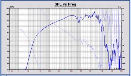
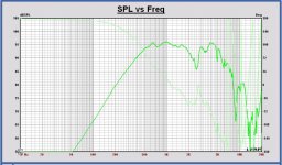
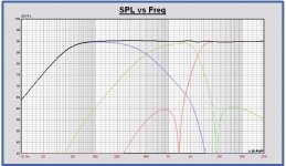
The procedure is as follows: you measure an in-box raw driver and produce a .frd file of the measurement. Than you start with a more or less textbook filter connected to the driver and choose a so called target function. The latter is the desired textbook acoustic output, eg. LR4 lowpass @ 750 Hz. You then either manually optimize the filter components until you have a match, or let the optimizer do the dirty work for you. I have on purpose left out a few steps. You can both use active analogue blocks or passive filters to do the optimization, but the you also need the impedance. After optimization you have the exact transfer function of your corrective filter. Transform that .frd or .txt file into filter coeffs and you can use Eq Apo (or Camilla) to do the filtering for you. There are more elegant ways, but this is the Basic Old School approach.
Tweaking with peaks or cuts also works, but is time consuming plus you need a proper GUI with overlay functions. Otherwise you keep on chasing your own tail.
Ok, so does the optimizer then gives you a suggestion for an active (or passive) analog filter? Or does it just give you a curve that you are expected to turn into something useful by yourself?The procedure is as follows: you measure an in-box raw driver and produce a .frd file of the measurement. Than you start with a more or less textbook filter connected to the driver and choose a so called target function. The latter is the desired textbook acoustic output, eg. LR4 lowpass @ 750 Hz. You then either manually optimize the filter components until you have a match, or let the optimizer do the dirty work for you. I have on purpose left out a few steps. You can both use active analogue blocks or passive filters to do the optimization, but the you also need the impedance. After optimization you have the exact transfer function of your corrective filter. Transform that .frd or .txt file into filter coeffs and you can use Eq Apo (or Camilla) to do the filtering for you. There are more elegant ways, but this is the Basic Old School approach.
No, you have to start with a given topology. The more components you throw in, the more freedom the Optimizer has to achieve the desired result. I believe MachinaXP, which has its own thread here on Diya, is the only programme that does all this fully automatically, leading to rather complex passive filters. But that is no problem: the filter design itself is only the vehicle you use to find the needed corrective filter transfer function.
Ok, then one more question. Is the goal to in the end run the finished speaker with dsp, or is dsp only a tool on the way towards a final passive or active analog filter?
This may not exactly answer your question, but an easy ready-made solution is to use JRiver Media Center (JRMC) for active crossover duty. It also is a media player and a hundred other things besides 🙂 I use a "TV Box" Windows PC that has HDMI out. I use outboard DAC and amps, but I think this would work as an input to a HTR that had 7.1 outs. Have not tried that. This works especially well if you use the PC/JRMC as the "source" as well. At USA prices at least, this means you could have a cheap PC (e.g. Pipo X9 about $150), JRMC ($50), and a HTR of your choice ($300 ?) and you have a fully active XO solution for $500 not counting speakers and cables. Only tricky thing there is HTR seem to want speakers to be around 6-8 ohms.
To provide a bit more information on my system -
I run everything on a Windows PC, which is my 'Media server' connected to the TV via HDMI.
All my Audio and Video files are cataloged on it, it also does all the processing.
Output is to my Xonar USB soundcard, I only use 6 of the 8 (7.1) channels because that's all I need.
This then goes to a 6 gang potentiometer for a passive volume control. So you always have full digital resolution if you want it. Or you can set the volume pot 'approx' and fine tune volume digitally.
Then it goes to my 4 stereo amps, 2 treble channels, 2 mid, and 2 bass feeding both sides of 2 amps for doubled bass drivers.
For a player I use 'Foobar'.
As well as the crossover filters, my channels include corrections for individual drive units and the room. In both amplitude and phase.
I have an individually calibrated UMIK-1 microphone to measure these.
I have heard a good few 1/4 million dollar systems at Hifi shows, and used to be a Professional sound engineer when I was younger.
My system works well. It can be adjusted to +/-3dB 20hz-20Khz IN ROOM.
But sounds much better with a 'House curve'.
It has minimal phase swings. People argue about if phase matters - but only when they haven't heard a good minimal phase system. The biggest difference is in percussive sounds. All the frequencies arrive close together in a 'smack' instead of Group Delay smearing them over 10's of milliseconds.
To answer HenrikEnquist question: it simply depends on what the user finally prefers. Some use the DSP as a development tool only, and then build it analogue (active may be somewhat cumbersome with complex topologies including gyrators) others use the DSP as a final solution. Of course the DSP version offers additional bonusus such as phase and room corrections. But the audio world -including the diy scene- is rather conservative: relatively few people make use of any form of room correction, convolution, Harman or House curves etc. Most here seem to stick to A/B amps and passive filtering, not to mention the use of totally uncorrected full range drivers.....
It also depends on where you start from.
If you can already play audio files from a computer, then it's simpler to carry on that route.
Although the way I've gone may seem complicated; in some ways it's simple -
it's mostly measure, then adjust slider controls. There's no circuits to design or build.
I previously built LR4 active crossovers for my system and had them for ~ 20 years. The FIR filters are as big an improvement over analog active, as active is over passive crossovers.
So you kind of leap an entire generation of technology, and get in at the front - with actually less work 🙂
Plus you can experiment, with and change crossover frequencies and lots of other things to zone in on 'perfection'. If you built them in hardware and changed your mind - you'd be pretty sad - I know, done it.
BTW every room has a 'House Curve', you just don't see it until you measure.
Every room will have differences between peaks and troughs 15dB +
It's genuinely shocking the first few times you measure.
You think you have these good speakers +/-3dB whatever. Then you find 20dB differences in the room when you get the mic out.
Every room will have differences between peaks and troughs 15dB +
It's genuinely shocking the first few times you measure.
You think you have these good speakers +/-3dB whatever. Then you find 20dB differences in the room when you get the mic out.
Ok, so let's split this into a few separate use cases.To answer HenrikEnquist question: it simply depends on what the user finally prefers. Some use the DSP as a development tool only, and then build it analogue (active may be somewhat cumbersome with complex topologies including gyrators) others use the DSP as a final solution. Of course the DSP version offers additional bonusus such as phase and room corrections. But the audio world -including the diy scene- is rather conservative: relatively few people make use of any form of room correction, convolution, Harman or House curves etc. Most here seem to stick to A/B amps and passive filtering, not to mention the use of totally uncorrected full range drivers.....
- Prototyping while designing a passive crossover
- Prototyping while designing an active analog crossover
- Designing and implementing a digital crossover
For case 1 and 2, I see how it could be useful to simulate a crossover to try it out. That could be done with either FIR or IIR, and it would make sense for LspCad etc to be able to export a filter. I would go for FIR since it's much less work to generate an impulse response than to create a set of IIR coefficients.
For case 3, the route via optimizing an analog compensation circuit that is only used to make the cad software spit out a correction curve seems strange. I would just export the acoustic frequency response of the driver, and use some other tool to create the compensation as either IIR or FIR. Matlab and Octave are both good choices. Maybe Rephase can be used also, haven't tried it much. If I wanted to do the compensation using a bunch of biquad shelves, peaks and notches, I would use REW since it has a tool do do this, either automatically or manually.
Nope, it only has the standard ones like peaking, shelves, notches etc. But it can import .frd and has a nice interface for viewing the effects of adding and modifying filters.REW does not contain user configurable filter transfer functions to my best of knowledge?
- Home
- Source & Line
- PC Based
- How to Configure a 7.1 PC Soundcard as an Active Stereo Crossover?