I want to combine to left and right channels for my sub while keep the left and right remaining for my bookshelfs.
How do I do this?
How do I do this?
you need a filter and a summing amplifier (i assume low levek signals). possibly a buffer to phase shift the signal depending on the rest of your system.
this page seems decent based on a quick google search: Op Amp Summing Amplifier
this page seems decent based on a quick google search: Op Amp Summing Amplifier
If your sub is powered and only needs a line level signal and your power amp isn't operating in bridge mode, ie, has a common connection for the ground end of both main speakers, you could probably get away with just summing the channels via a pair of high value resistors and feeding that to the sub.
Does the sub expect a line level input? Does it have internal lowpass filtering?
We need more details to work with really. 🙂
Does the sub expect a line level input? Does it have internal lowpass filtering?
We need more details to work with really. 🙂
Last edited:
Here http://www.diyaudio.com/forums/solid-state/167363-mic-line-eq-preamps-15.html#post2350577 you will find a complete preamp schema. Look at the upper right corner. There is a very simple circuit that adds both channels and filters the signal, in order to feed the subwoofer (mono) output only with lower frequencies.
Some stereo car amps have a phased output on one channel, this allows easy bridging of the amplifier This also means that a 2.1 speaker system can be used, the 2 speakers in stereo, and the sub in mono bridge.
You can get cheap passive crossover kits for this use, usually with a pair of caps for the stereo hi-pass and a single inductor for the sub.
To get a 2.1 system you would need to invert the signal phase to one of the amplifier channels, You probably need an op amp circuit for this, or maybe you could get some signal transformers and rewire one out of phase.
The stereo speakers are wired as normal but with one channel reversed, The sub is wired across both the amplifier outputs as a bridge mode.🙂
Note Don't try this with a 4 ohm sub....
My cheap Sony sub uses a 2.7KOhm resistor for each channel to combine the signals to mono. For example, left channel to a 2.7KOhm resistor, another 2.7Kohm resistor for the right then join the two ends together and there's your mono signal.
Craig
Craig
Okay thanks for the advice, the sub is already filtered and is 4 ohm. So I'm thinking of just using a couple of resistors. That schematic, is it just the cap and that resistor or does it go further?
The "Generic" method used in pro audio (usually, creating a mono signal from a line level single-ended source, such as a CD player's analog RCA output jacks, for sound checks, etc while saving a console input, which are always in demand) goes like this:
Hot lead Line Level CH1 --> 47K ohm resistor -->
Hot lead Line Level CH2 --> 47K ohm resistor -->
[Solder the two resistor leads together] --> Hot lead Line Level Mono
Normally you can sum the Ground leads together without problems since they are common internally at your stereo line level output source; that's your ground lead Line Level Mono.
There are other ways, eg a DI Box which will be either transformer coupled or use a buffer circuit but it's not necessary for what you're planning to do, plus the "good" ones will run you $200+.
There may be good reasons to use a different value for the resistor, but the 47K is the value to use if you are unsure. Preventing DC with a capacitor is usually not needed for component audio equipment, but should be considered if your line level source is non-component gear, such as a portable mp3 player.
Last edited:
if you are correct that this is the normal "pro" method, then the "pros" are partially mono-ing their stereo signals.The "Generic" method used in pro audio
One should use a summing circuit to create a mono that does not affect the two halves of the stereo signal.
Last edited:
if you are correct that this is the normal "pro" method, then the "pros" are partially mono-ing their stereo signals.
One should use a summing circuit to create a mono that does not affect the two halves of the stereo signal.
It works fine for sound checks, doesn't hurt the line-level source (first rule ... don't break stuff). I don't know where else the stereo signal would be going, so I don't really see what's "affected". If they want a "real" mono signal, like in a radio station, there is a preamp or mixer there that has the summing circuit built in. Or, they can use two inputs to the console and use the console's summing circuit (pan each channel to centre for 2-ch mono out, or pan both left and send to 1 channel out, for example). But that extra input is probably useful doing something else.
Like I said, you can always buy or build something more elaborate, but there won't be out-of-phase information at the frequencies the sub cares about. A lot of subs with stereo line level inputs have exactly that kind of configuration right behind those two RCAs before it goes to the line level mono amp. Horses for courses.
Last edited:
and if the line level mono amp is configured as inverting then those two input resistors are the summing resistors of the summing circuit.A lot of subs with stereo line level inputs have exactly that kind of configuration right behind those two RCAs before it goes to the line level mono amp.
The impedance at the -IN pin of an inverting opamp/poweramp/chipamp is near zero.
Feed one 47k to that -IN pin and you have a conventional single channel inverting amp where the 47k determines the gain.
Instead attach two 47k to that -IN pin and both 47k are the feeds to the summing node The channel gains of each of the two inputs are determined by one or other of the 47k.
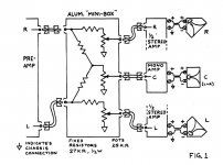
Paul Klipsch used a similar circuit when he ran a Cornwall centre from a stereo signal with Klipschorns in the corners. Although in that case the gains of each amp are similar so he used 27 K ohm resistors, and attenuated the output to the L + R as well. Perhaps he's not "Pro" enough, though.
Attachments
Last edited:
That is different.
The two resistors feeding the sub channel create crosstalk in the two stereo channels.
That is almost the same as what you said "pros" do.
If you want to preserve your stereo signal for the two channel reproduction then none of your proposed circuits achieve that.
The two resistors feeding the sub channel create crosstalk in the two stereo channels.
That is almost the same as what you said "pros" do.
If you want to preserve your stereo signal for the two channel reproduction then none of your proposed circuits achieve that.
I already said. See posts 9 & 11.
Use an inverting amp as a summing node. This gives your mono signal and leaves the stereo unaltered.
The inverting amp can be an opamp, or an MFB filter, or a poweramp. There's many ways to configure it.
All rely on the effective zero impedance at the -IN pin.
Use an inverting amp as a summing node. This gives your mono signal and leaves the stereo unaltered.
The inverting amp can be an opamp, or an MFB filter, or a poweramp. There's many ways to configure it.
All rely on the effective zero impedance at the -IN pin.
...
One should use a summing circuit to create a mono that does not affect the two halves of the stereo signal.
and if the line level mono amp is configured as inverting then those two input resistors are the summing resistors of the summing circuit.
The impedance at the -IN pin of an inverting opamp/poweramp/chipamp is near zero.
Feed one 47k to that -IN pin and you have a conventional single channel inverting amp where the 47k determines the gain.
Instead attach two 47k to that -IN pin and both 47k are the feeds to the summing node The channel gains of each of the two inputs are determined by one or other of the 47k.
I already said. See posts 9 & 11.
Use an inverting amp as a summing node. This gives your mono signal and leaves the stereo unaltered.
The inverting amp can be an opamp, or an MFB filter, or a poweramp. There's many ways to configure it.
All rely on the effective zero impedance at the -IN pin.
The last post was actually a solution, combined with the details in the second post. The first, taken by itself ... my mind reader is broken, and it never worked that well in the first place. My guess is the OP's works about as well. Thanks for clarifying.
Last edited:
If your sub is powered and only needs a line level signal and your power amp isn't operating in bridge mode, ie, has a common connection for the ground end of both main speakers, you could probably get away with just summing the channels via a pair of high value resistors and feeding that to the sub.
Does the sub expect a line level input? Does it have internal lowpass filtering?
We need more details to work with really. 🙂
I have the same issue. I am also trying to combine the left and right channels out of my sound device without making everything mono? I have a powered sub that has line level inputs and I want to retain my stereo field but send a signal from both channels into that sub. FYI the sub has a low pass on it already so I can send a full range signal to it, I just need to figure out the best way to combine the signals using a common ground and possibly a resistor on the L-R leads? I am confident one of the geniuses on this site will know how to do it.
Exactly how would I sum the channels via a pair of high value resistors? Which resistor? and how would I connect them? Solder?
Thanks
if you are correct that this is the normal "pro" method, then the "pros" are partially mono-ing their stereo signals.
One should use a summing circuit to create a mono that does not affect the two halves of the stereo signal.
Well much "pro" circuitry use very low output impedance drivers (sub ohm), so a couple of 47k resistors is neither here-nor-there. Low impedance outputs are used as they reduce capacitive crosstalk from adjacent channels. With as low as 100 ohm outputs and a few pF of crosstalk from a 10V 10kHz signal you'd see maybe 0.2mV crosstalk (-70dBu). Sub-ohm outputs take this right down.
Another issue with the 47k resistors is the Johnson noise they create, although pro signal levels are nice and high which should mitigate this effectively.
Incidentally a little cross-feed between stereo channels is very hard to detect, -30dB separation is plenty in practice I believe.
What the pros use is XLR and I usually wire Left Hot to pin 2 & Right Cold to pin 3 and that gives me a mono signal with the same level.
An Acoustic Simulator for Headphone Amplifiers | HeadWize
Modified Linkwitz Crossfeed
There are a couple of crossfeed circuits aimed at headphone users, with some filtering, that are worth a shot
Modified Linkwitz Crossfeed
There are a couple of crossfeed circuits aimed at headphone users, with some filtering, that are worth a shot
- Home
- Amplifiers
- Solid State
- How to combine the left and right channels with out making everything mono?