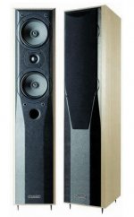
Having been inspired by Rod Elliots article on Bi-amping I have decided I am going to build an active crossover for my Mission 703e s. The only problem is I don't know what crossover frequency to use. Does anyone know where I might find such information? Or if there is a way of calculating it?
Any info is much appreciated
jnxw2
Any info is much appreciated
jnxw2
Good question
Hi,
I think you are doing a good thing.
Is not difficult. Are they two ways?
You should find out which is the crossover point based on the crossover parts and impedance of the drivers.
Would be even better if you could measure the drivers, that would be very good, because then you could choose the trade-offs and not the original designer.
Any info about the speaker?
Which filter do you plan to use?
My modest knowledge is at your service
BTW the esp article is very inspiring
The starting point can be the present XO frequency set by the passive crossover, anyway bi-amplification implies that you open your speaker and bring outside speaker terminals directly, completely eliminating the passive xover; if the speakers allow bi-wiring you can take advantage of the double terminals, otherwisa you need to find a solution.
Cheers
Andrea
Cheers
Andrea
You can use a sine wave generater like in winisd the xo point is when output is even from both drivers, this will give you a starting point then use your ears and wot test equpment youve got. Take your time and do a few times write things down as you go. good luck Max.
In fact I made a mistake they are not 703e but 773e s 🙄
The cones are approximatly 10.5cm or 4in in diameter. I am not sure though if they recieve the same signal or if one does mid and the other does bass??
The speakers have two sets of terminals and I have already taken the passive XO out to have a look, unfortunatly the value of the inductors isnt marked on it. I dont have my digital camera with me but i should be able to post a picture of it tomorrow if that would help.
cheers
jnxw2
Attachments
hold on there
when you start from scratch you usually have some semblance of the response curve of the driver from the manufacturer -- I did say "semblance" since the conditions are often ideal which isn't what you will experience at home.
One thing which I have been thinking of doing is a "State Variable" filter using digital pots to set the low pass, band pass and high pass filters -- one could adjust the performance on the fly by adjusting the digital potentiometers.
Analog Devices has one such design on the PDF for their dual 8-bit DAC, but, of course, you could use a digital pot from Analog, Dallas (Maxim) etc.
Don't try to second guess a good designer. The electrical crossover may not be (probably will not be) a simple, symmetrical function. Get in there and measure the electrical transfer function of the crossover at each of the driver terminals, then design the electronic crossover to duplicate it. Otherwise, you'll end up with a speaker that sounds different but almost certainly NOT better.
im pretty new to this, is there an easy way to measure the electrical transfer function of the crossover with a DMM and sinewave generator?
jnxw2
jnxw2
If your DMM has a spec'd frequency response that's flat out to 10kHz or so, then it's a piece of cake (though a bit tedious)- feed the signal generator to your amp, adjust the volume to something reasonable (not too loud, not too quiet, something on the order of a couple of volts), then measure the voltage at each driver terminal at a number of frequency points. Plot the results for each driver on a log-log graph, and you'll have a good idea of what the crossover will have to do.
If your DMM is not spec'd to be flat over the audio range, borrow an oscilloscope or an AC voltmeter. Or get serious and use some MLS or FFT software and do it with your computer. This will give you MUCH faster and cleaner results.
Keep saying this mantra: "Electrical crossover transfer functions are not the same as acoustic crossover transfer functions."
I strongly recommend the speakerworkshop, I think would be perfect for you.
Then, your task will be easier.
Then, your task will be easier.
Ok my DMM has a frquency range of only 40-400hz but i had nothing else to do so measured the voltage at the terminals anyway and got this:
Frequency LF Voltage HF Voltage
1000 0.045 0.007
2000 0.033 0.016
3000 0.027 0.025
3100 0.026 0.026
4000 0.025 0.036
5000 0.026 0.048
10000 0.01 0.069
As i am no expert are these results useless because the DMM isnt calibrated over the frequency range or would i get away with assuming 3100Hz as the crossover freq?
jnxw2
PS I plan on making the ESP 24dB/octave Linkwitz-Riley crossover
The frequency seems reasonable, given the size of the drivers.
If I remember right, the esp crossover doesn't have variable freq. has it?
Is far from the equal power value (300Hz) but I don't think it really matters.
Which are the values (and scheme) of the crossover? This will tell us if both woofers are in parallel, or is a 2 1/2 system.
If I remember right, the esp crossover doesn't have variable freq. has it?
Is far from the equal power value (300Hz) but I don't think it really matters.
Which are the values (and scheme) of the crossover? This will tell us if both woofers are in parallel, or is a 2 1/2 system.
The frequency seems reasonable, given the size of the drivers.
If I remember right, the esp crossover doesn't have variable freq. has it?
Is far from the equal power value (300Hz) but I don't think it really matters.
Which are the values (and scheme) of the crossover? This will tell us if both woofers are in parallel, or is a 2 1/2 system.
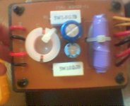
Sorry about the quality of the image but like i said i dont have my digital camera here today. On the left are the inputs on the right or the outputs, when i measured the voltage on the outputs for both the drivers they were always identical so i am assuming they recieve the same signal.
Neither inductor has any markings on them. the top resistor is a 5W 1.5 ohm. The bottom one is 5W 12ohm.
The dark blue capacitor is 4.7uF 50V +/-10% and the other one is 20uF 50V
I hope this is some help
jnxw2
If I remember right, the esp crossover doesn't have variable freq. has it?
Is far from the equal power value (300Hz) but I don't think it really matters.
Which are the values (and scheme) of the crossover? This will tell us if both woofers are in parallel, or is a 2 1/2 system.
Sorry about the quality of the image but like i said i dont have my digital camera here today. On the left are the inputs on the right or the outputs, when i measured the voltage on the outputs for both the drivers they were always identical so i am assuming they recieve the same signal.
Neither inductor has any markings on them. the top resistor is a 5W 1.5 ohm. The bottom one is 5W 12ohm.
The dark blue capacitor is 4.7uF 50V +/-10% and the other one is 20uF 50V
I hope this is some help
jnxw2
Attachments
It isn't just a matter of the crossover frequency, it's a knowledge of the entire transfer function of the crossover. You can't determine that by just looking at the crossover board, you have to go in and measure it.
If you want to have a positive outcome to this project, bite the bullet and get a calibrated way to measure what your target is and (while constructing) how close you're coming to it. The investment is minimal.
If you want to have a positive outcome to this project, bite the bullet and get a calibrated way to measure what your target is and (while constructing) how close you're coming to it. The investment is minimal.
I think that if we know the crossover as mission did it, we'll have a useful clue about what someone decided was good. Then you'll have to take the decision
Maybe the big resistor is for impedance compensation.
Is it possible to get the scheme of the board, following the cooper tracks?
Obviously, not only the crossover point is the target, the slopes are too.
Maybe the big resistor is for impedance compensation.
Is it possible to get the scheme of the board, following the cooper tracks?
Obviously, not only the crossover point is the target, the slopes are too.
ok i have downloaded speakerworkshop, ill have a go at it at the weekend and see if i can work it out
jnxw2
jnxw2
It's a nice software, but it won't work properly if you don't set it up properly. I almost gave up due to the meaningless data I was getting. After the jig was built, it worked very well.
But I think that deducing the crossover scheme from the board could be also helpful.
But I think that deducing the crossover scheme from the board could be also helpful.
.
Unless you know the complex impedance of the drivers, there's no way that examining the crossover board will tell you much.
But I think that deducing the crossover scheme from the board could be also helpful.
Unless you know the complex impedance of the drivers, there's no way that examining the crossover board will tell you much.
SY said:.
Unless you know the complex impedance of the drivers, there's no way that examining the crossover board will tell you much.
Of course.
BTW, has any of you tried passive biamplification?
- Status
- Not open for further replies.
- Home
- Loudspeakers
- Multi-Way
- How to choose active XO freq?