Well if you hear a difference with the MAC power supply then this DAC is not competent.
You can't fool physics.
Jan
Please Jan can you explain your point of view with this. Thanks
You can't fool physics.
Jan
Please Jan can you explain your point of view with this. Thanks
You're in the wrong thread. Were is the original?Well if you hear a difference with the MAC power supply then this DAC is not competent.
You can't fool physics.
Jan
Please Jan can you explain your point of view with this. Thanks
Jan
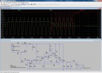
With an output to low (short) there is no base current for Q4 via the zener nor for Q5 via R9.Disconnecting D4 breaks the loop as well as R9. The input circuit seems to place the regulator in hiccup mode during a shorted output. The asc is attached for anyone who wants to play.
So now the collector of Q5 has positive pulses from the base drive via C6 making Q4 conduct followed by the rest, Q1Q2Q3.
Rather bad condition.
Mona
The signal is digital all the way up to the DAC. So when you muck up anything with the power supply, you can get things like jitter on the signal. A competent DAC should be able to take care of the jitter so that the signal is not audibly influenced.Well if you hear a difference with the MAC power supply then this DAC is not competent.
You can't fool physics.
Jan
Please Jan can you explain your point of view with this. Thanks
Jan
it´s not a startup circuit , but a switch-off circuit; as soon as 50hz fails, the feedback transistor with it´s emitter to gnd is driven such that the supply turns off.Yes, I noted that too. Maybe it really does need a start-up circuit.
Some experimental versions of the superreg needed it too.
Happens sometimes if the reference is fed from the output.
Does not make it a bad supply though.
Jan
Ah yes, you are right, it provides a quick turn-off.it´s not a startup circuit , but a switch-off circuit; as soon as 50hz fails, the feedback transistor with it´s emitter to gnd is driven such that the supply turns off.
Probably the circuit it powers isn't stable at lower voltages.
Mona
during turn off the NPN driver is challenged in it´s VBE as the base is drawn negative vs the emitter that stays on 12V from the output capacitance. so the NPN base will zener around 5V, and probably it´s base current will exceed temporarily the maximum current allowed. over time this will result in reduced beta.
Yes, that's what I thought based on an informal analysis (see above), but another member dug deeper and went as far as simulating it, and only found minor differences with/without the additional circuit.Ah yes, you are right, it provides a quick turn-off.
Probably the circuit it powers isn't stable at lower voltages.
Mona
I am pretty sure that the sim is accurate; there might be a typo in the component values, causing the lack of effectiveness, but the main goal does seem to be a quick and clean shutoff anyway
Hello
I have a Pyramid power supply which gives 13.8V . I adjusted the pot inside the PS but can get near 13.2volts at lower point. I want 12 volts to feed a Mac mini. This circuit seems interesting because it uses discrete parts instead of ubiquitous 78xx with a pass transistor. Any other mods suggestion ? Thanks
Send me a PM.
What is the current rating for that Pyramid supply?Hello
I have a Pyramid power supply which gives 13.8V .
Mac Mini original supply is rated "150 Watts" , meaning 12.5A
A single 2N3055 will be hard pressed to deliver more than 10A , Real World conditions, but I am more worried about its dissipation.
Lowering output voltage from 13.8 to 12V can easily double it, depending on difference between raw rectified voltage and 12V
Personally I would not risk an excellent expensive computer for the sake of an imaginary "sound improvement".
What if 2N3055 shorts (which is a very real possibility) and sends raw 16-18V DC to that poor Mac Mini?
That will not happen.during turn off the NPN driver is challenged in it´s VBE as the base is drawn negative vs the emitter that stays on 12V from the output capacitance. so the NPN base will zener around 5V, and probably it´s base current will exceed temporarily the maximum current allowed. over time this will result in reduced beta.
The fast turn-off starts when Q1 (reference original shematic) doesn't conduct anymore. But as long as the output voltage is over 5V or so the Q1 base is kept positive via R2.
So, no quick turn-off exept for the last 5V , seems rather useless ??
Mona
Q1 is a protection circuit that shuts down the output when it is shorted. The AC input is a pulsed restart attempt.
As others have pointed out, no change in R7, R10 etc will reduce the voltage below DZ1+Q2 = 12 +0.65 = 12.65. A better design would be to add a base series resistor to Q2 so that R10 could be zero, but perhaps a wider voltage range is not desirable.
As others have pointed out, no change in R7, R10 etc will reduce the voltage below DZ1+Q2 = 12 +0.65 = 12.65. A better design would be to add a base series resistor to Q2 so that R10 could be zero, but perhaps a wider voltage range is not desirable.
- Home
- Amplifiers
- Power Supplies
- How to change the output voltage from 13.8V to 12v with this circuit