Dear friends!
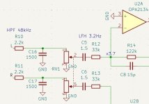
I am assembling a headphone amplifier. I have a question: how to correctly calculate the value of the potentiometer RV1? I heard that it should be about 10 times less than the input resistance of the amplifier. In my case, the input resistance is determined by the value of R12 and is equal to 33k. Then I need a potentiometer of 3.3k? But everywhere where I studied the circuits of similar amplifiers, they recommend a potentiometer value from 10k to 100k.
How to choose correctly?
PS. Input signal goes from PCM2704 DAC (recommended output impendance 10k or more).
Attachments
Last edited:
If you use 3k3 you will lose 40% of the signal across R10. I would lose the input filter circuit, make the pot the input loading, and make the 48kHz filter part of the opamp NFB loop. You’re compromised in how big the pot can be because of the inverting amplifier following, and how small it can be because of what loading the source needs.
Ok. I can remove R10 and C16 and change the value of C8 to 27pF. After that I can use 3.3k pot. Am I right?I would lose the input filter circuit, make the pot the input loading, and make the 48kHz filter part of the opamp NFB loop.
But what will be the input amp impedance in this case? 3.3k? That's too little for my signal source. I need at least 10k. Or it still will be 33k?
You can use a 100k linear pot, which loaded by 33k will give you a roughly log taper response, with the added advantage that dual linear pots usually have much better balance between gangs than log pots. For details of this technique, see here: http://www.geofex.com/article_folders/potsecrets/potscret.htm

Is there a way to know impedance without assembling the amp?You could investigate an active gain stage where your present 33k is the pot.
10 times more, not less!...I heard that it should be about 10 times less than the input resistance of the amplifier. In my case, the input resistance is determined by the value of R12 and is equal to 33k...
With R10 and C16 removed, the impedance seen by the preceding stage is:
Rin=RVu+(RVl//R12) where RVu is the upper section of RV1 and RVl the lower. "//" means "in parallel with".
So: Rin=RVu+(1/RV1+1/R12)^(-1)
It turns out that the minimum impedance is when the wiper is at the top of RV1, i.e. RVu=0. We can plug in different values for RV1 to see which values keep the minimum impedance above 10k.
Rin(min)=(1/RV1+(1/R12)^(-1)
If R12=33k, different values of the potentiometer result in the following Rin(min) values:
RV1 Rin(min)
10k 7k7
33k 16k5
47k 19k3
100k 24k8
I assume RV1 is intended to function as a volume control, in which case I would suggest a 47k log pot is the most suitable.
With C8=27p, the LPF is correctly set to c. 48kHz.
Last edited:
You can use a 100k linear pot, which loaded by 33k will give you a roughly log taper response, with the added advantage that dual linear pots usually have much better balance between gangs than log pots. For details of this technique, see here: http://www.geofex.com/article_folders/potsecrets/potscret.htm
A 100k lin pot is a great idea in principle, but will it provide enough attenuation to be a useable volume pot? Here is its gain plot:
At max rotation the gain is c. +11dB. At 0.5 rotation the gain is 0.5dB, which is only -10dB relative to the max output. It's a nice smooth curve, but is this enough attenuation? I would suggest that a useable target for 0.5 rotation would be -20dB relative to the max output, double what a 100k lin pot would provide in this circuit.
No, read carefully. The pot should be less than the load impedance and more than the source impedance. The original statement was "...I heard that it should be about 10 times less than the input resistance of the amplifier."10 times more, not less!
Being the general audio principle of low impedance drives high impedance (for least signal loss).
However its not that simple in reality - large values of potentiometer might increase distortion for instance by converting the amp's non-linear input current into signal.
Also higher values of resistance lead to more voltage noise added to the source.
The truth is that an active volume control can perform better and certainly be less of a compromise.
When I made that erroneous statement, I had in mind that the potentiometer needs to be larger that the 33k resistor, not that the output imp of a preceding stage needs to be 10x larger than the i/p imp of the following stage. So my apologies are due for misreading the first post and misleading people.
I agree that an active volume control can be less of a compromise; the circuit as presented is, arguably, less than optimum. However, the OP asked a question specifically about this circuit and how to size the potentiometer. He did not ask for alternative circuits.
Whether, in the present instance, the potentiometer is an element of the preceding stage (suggesting a lower pot value) or is part of the input structure of the following stage (suggesting a larger value) is, I suggest, something of a moot point, and not a particularly useful way of looking at the issue in this case.
The OP specifies that the preceding DAC should see a minimum impedance of 10k. A pot with a value of 10k would present a minimum impedance of 7.7k, which would probably be OK but is not in spec. A potentiometer of 47k results in a minimum impedance of around 20k and is probably the best bet. I suggest a good quality 47k log pot would give the best result. The max noise resistance seen by the inverting input of the op amp works out at 39k.
Many contributors here turn their noses up at log pots because of a perceived risk of poor tracking between the channels. An alternative solution with a linear pot would be: 100k lin potentiometer; R12=13k; R14=47k; C8=68p. With these values, the minimum input impedance is 11.5k; the max gain is x3.6; the attenuation at a rotation of 0.5 is a satisfactory 15dB rel. to the max output; the turnover frequency of the LPF is 48.7kHz; the max noise resistance seen by the inverting input of the op amp is improved at 27k. But this way does require a number of changes to the components around the op amp.
Your basic input impedance to the amp is 33 kohms. The above suggestion of 47 or 50 kohms is what I'd do so the driving stage doesn't get overly loaded down. If this is a new build, I'd go for a stepped attenuator made with individual resistors so you can set up a log curve and even have a loudness switch if you want it. That avoids the tracking problem and, IMHO, they sound better due to higher quality resistors.
- Home
- Design & Build
- Electronic Design
- how to calculate volume potentiometer value?