To a first approximation, compare the gm of the two tubes. The feedback resistor will scale by the same proportion (i.e., the tube with the bigger gm will have the larger feedback resistance).
So ECC81/12AT7 as a μ of 60 and Rp or Ri (is that the same ?) of around 11k
gm=μ/Rp=0,005 = 5
And 5842 μ of 41 and Rp of 1700
gm=u/Rp=0.025 = 25
So the value of resistance for Rfb should be larger in value than for the ecc81?
gm=μ/Rp=0,005 = 5
And 5842 μ of 41 and Rp of 1700
gm=u/Rp=0.025 = 25
So the value of resistance for Rfb should be larger in value than for the ecc81?
Larger value resistance=less feedback for the tube with more gm?So the value of resistance for Rfb should be larger in value than for the ecc81?
Sorry, I thought you were talking about a global feedback resistor.
If you mean a cathode bias resistor then to a first approximation, compare the mu of the two tubes. Rk will scale inversely by the same proportion (higher mu = smaller Rk)
ECC81/12AT7 has a μ of 60; Rk was 220 ohms;
5842 has a μ of 41;
220 * 60/41 = 351 ohms.
If you mean a cathode bias resistor then to a first approximation, compare the mu of the two tubes. Rk will scale inversely by the same proportion (higher mu = smaller Rk)
ECC81/12AT7 has a μ of 60; Rk was 220 ohms;
5842 has a μ of 41;
220 * 60/41 = 351 ohms.
Last edited:
Erm. I believe Merlin meant different output tubes.
Rfb determines output tube's effective plate impedance and also output stage's input impedance. Doesn't really have anything to do with the driver (except the driver should be able to drive that input impedance, but if 12AT7 can do it...)
Rfb determines output tube's effective plate impedance and also output stage's input impedance. Doesn't really have anything to do with the driver (except the driver should be able to drive that input impedance, but if 12AT7 can do it...)
It's the Schade feedback resistor. Or shunt feedback?Sorry, I thought you were talking about a global feedback resistor
Attachments
Last edited:
Hi Bas,
If I understand the Schade-style feedback correct (and I hope others will correct me if I miss something), the feedback ratio can be calculated as
beta = Rs / (Rs + Rfb), where Rs is the parallel resistance of Ra (anode resistor first stage), Rg of second stage, rp of 12at7 triode.
Rs = Ra//Rg//rp
as the cathode resistor is not bypassed, that should be included as well:
Rs = Ra//Rg//(rp+(1+u)*Rk)
If you change the tube (and hence Rs), you can adjust Rfb accordingly to get the same amount of feedback. If you aim for 10% feedback, Rfb should be 9*Rs.
I hope I have not one of my usual hiccups here but at first glance that's it. Am I missing something?
Cheers,
Martin
I would say that together with Rfb, R23 and output tube gm, the plate load has to be considered as well, or better the swing at the plate and the swing at g1, because Rfb will be virtually lower the higher the plate swing is.
...am I right?
...am I right?
Hallo Martin,
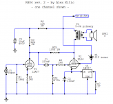
These are the values for the 5842...And my plate resistor. Cathode resistor and Grid Leak resistor of the EL84 grid.
Ra=12000
Rg=470000
rp=1700
u=41
Rk=133
Rs=Ra//Rg//(rp+(1+u)*Rk)
12000//470000//(1700+(1+41)*133)
1700+(42*133)
(1700+5586)=7286
Rs=12000//470000//7286
I'm not familiar with the // operand though...
Last edited:
Hi Bas,
the // means "parallel" as in parallel connection of resistors.
So basically 1/Rtotal = 1/R1 + 1/R2 + 1/R3...
Rp seems quite low for the 5842.
With your values, I get 4490 Ohm for Rs.
Now, you would need to repeat that exercise with the values of the original RH84. I would expect to get much higher Rs for the 12AT7 in this circuit, guessing around 12-15k (not calculated!).
Once you know the feedback ratio beta (beta = Rs / (Rs + Rfb) for the original RH84, you can adjust Rfb to give the same beta for the 5842 Rs of 4490 Ohm.
Cheers,
Martin
Last edited:
Thinking about it...
Is the 5842 a good choice for Schade-style feedback?
I am far from being an expert, so if anyone objects, I would not be offended.
As far as I understand the principle of this type of feedback, wouldn't you want to choose a driver tube with high Rp?
With low Rp, you would have to either limit the amount of feedback to very few percent or you put quite a heavy load on the driver tube.
Or am I missing something (honest question)?
Maybe someone who has designed similar circuits wants to chime in.
I seem to remember that some people advocated the use of pentodes as driver in this type of circuits (high internal resistance), though.
As I have not build and experimented with an RH84 amp, I can't comment on (or even dare to judge) real life performance. Many forum members seem to enjoy their original versions.
Cheers,
Martin

Using the values of the schematic you posted and wildly guessing an anode current around 8mA for the 12AT7 (I actually used a Rp of 12.5k in my calculation), I would get 11.84k for Rs. So with 100k Rfb, beta would be around 0.11.
With Rs = 4490 for the 5842, I would arrive at 36k for Rfb.
I hope this helps.
My comments about the choice of the 5842 are theoretical. Please don't let them discourage you to breadboard and test how it works.
Maybe I should try a RH84 myself at one point (too many projects, too little time). 😀
With Rs = 4490 for the 5842, I would arrive at 36k for Rfb.
I hope this helps.
My comments about the choice of the 5842 are theoretical. Please don't let them discourage you to breadboard and test how it works.
Maybe I should try a RH84 myself at one point (too many projects, too little time). 😀
I think you are absolutely correct. (from reading about this type of feedback today) I just tried it...and the amp sounded good. Changing the amp to use LM317 instead of resistors in the cathode of the EL84. I noticed that I had 11K as Rfb resistor...and that struck me way off.. (built the amp years ago)As far as I understand the principle of this type of feedback, wouldn't you want to choose a driver tube with high Rp?
Anyway...I am going back to ecc81 because 5842 is "unobtainium" and/or expensive.
Thanks for all your help. I'm going to listen a couple of weeks with around 36k and then go back to the original RH84.
PS...What I find strange is that the 5842 with less u...sounds much louder than the ecc81.
The plate resistance, rp, of a triode is increased by the factor of (u x RK) . . .
but Only when RK is un-bypassed.
That is why you will see most RH amp schematics do Not bypass RK on the input triode.
It is not primarily to get rid of bypass cap "grunge", instead primarily it is to raise the value of rp.
Therefore, the amount of negative feedback (gain reduction) in an RH amplifier is dependent on these things:
1. rp + (u x RK) effective dynamic plate resistance
2. Rp plate load resistor
3. Rf Schade feedback resistor
4. Rg of the output stage
Change the tube, or any of the other 3, and the amount of negative feedback, and amount of gain changes.
. . . Simple
Oh, is that (u + 1) x RK, my old brain can not remember. Does not make a lot of difference if the u is high.
As to the existence or not, amount thereof, and your possible worrying about bypass cap "grunge", I leave that up to you, the reader.
That is another heated discussion, not to be discussed in this thread.
Last edited:
Bas Horneman,
5842 lower u
lower (u + 1) x RK
lower rp
lower effective plate resistance
So more gain with the same feedback resistor (gain set by feedback loop)
12AT7 higher u
higher rp
higher (u + 1) x RK
higher effective plate resistance
less gain with the same feedback resistor (gain set by feedback loop)
yes?
no?
One more factor to the negative feedback that I forgot:
The parallel impedance:
rp of the output tube; and the impedance of the primary winding inductance, distributed capacitance (and including the reflected load from the secondary of either a resistor load, or a loudspeaker) . . .
That complex impedance is in series with the schade feedback resistor.
The parallel impedance:
rp of the output tube; and the impedance of the primary winding inductance, distributed capacitance (and including the reflected load from the secondary of either a resistor load, or a loudspeaker) . . .
That complex impedance is in series with the schade feedback resistor.
Excellent point. Also,
I wonder if folks who'd calculated the load that the driving valve actually sees (remembering that the shunt feedback resistor is effectively divided by output stage gain) would be so enamoured of shunt feedback.
It's a good place to pick up feedback but not a great place to apply it (triode anode).
All good fortune,
Chris
Thanks for the education 6A3 summer and all the others!
I fitted a 47k Rfb. And the sound is subjectively warmer. (Better harmonic distribution) Forgive me for getting audiophile on you guys.
I fitted a 47k Rfb. And the sound is subjectively warmer. (Better harmonic distribution) Forgive me for getting audiophile on you guys.
- Home
- Amplifiers
- Tubes / Valves
- How to calculate Rfb in an RH84 amplifier