Hello to all!
One question I have for a long time and still can not completely solve is how to calculate the maximum power that an output transistor in an amplifier can consume in a given circuit.
How do I calculate this power in a class B amplifier and in a class AB amplifier?
What measurements should I do to find out if an amplifier is biased in class B or AB?
If in an output stage of an amplifier specified as being able to deliver up to 100W I have four transistors is correct to say that this power is divided equally between the transistors and each will consume 25W?
Thanks to everyone who can help me.
Here's a good introduction...
http://www.updatemydynaco.com/documents/Class_B_Amplifier_Dissipation_Calculations.pdf
there are other factors, but this would be a good place to start.
http://www.updatemydynaco.com/documents/Class_B_Amplifier_Dissipation_Calculations.pdf
there are other factors, but this would be a good place to start.
Here's a good introduction...
http://www.updatemydynaco.com/documents/Class_B_Amplifier_Dissipation_Calculations.pdf
there are other factors, but this would be a good place to start.
I am not sure where the 0.45 came from in the middle of page 1.
I seem to get different numbers than this.
From the paper (page 3 example):
Max power diss = Vps*Vps / (19.75 * RL)
With 72V supply and 8R load this formula calculated to 32.81W
16.2Vrms into 8R= 32.8W
BUT
With 18Vrms, 8R load the power output is 40.5W
Current drawn from the supply is 18Vrms / 8R = 2.25A
I get a power drawn from the supply at 81W (72 * 2.25 / 2)
Power dissipation is 81W - 40.5W = 40.5W
I learned that max power dissipation was at 50% of maximum theoretical output:
Max power diss = Vps*Vps / (16 * RL)
(Both are calculating for class B...Quiescent current for class A or AB adds additional power dissipation)
Anyone else?
LOL
OK, that is where it came from.
I guess my question should have been:
Why is it there?
My calculations seem to differ.
🙂
OK, that is where it came from.
I guess my question should have been:
Why is it there?
My calculations seem to differ.
🙂
The whitepaper on updatemydynaco.com arrives at this result using a bit of calculus (oh no!):
Pin = Vps * (Vrms/RL) * (sqrt(2)/PI)
If you don't agree, what is the correct equation in your opinion?
Pin = Input power (Pin = Pout + Pdiss)
Vps = Total power supply voltage between V+rail and V-rail
Vrms = Sinusoidal RMS voltage across the loudspeaker (RL)
RL = Loudspeaker resistance
Can you think of a simple way to measure these quantities in a small LTSPICE simulation? If so, would you believe the simulation results? (Some folks never trust simulations)
Attachments
Irms is already the integration of the peak of a sine wave. (or half sine)
You have integrated the Irms.
Why integrate the current waveform twice?
Got to go on a bike ride now...
Later
🙂
You have integrated the Irms.
Why integrate the current waveform twice?
Got to go on a bike ride now...
Later
🙂
Last edited:
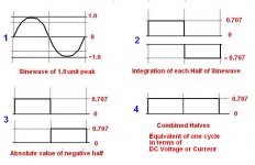
The 0.707107 of peak is 1 / (2 ^.5)
But is derived by simple (no calculus needed) math. (unless you count finding the sine of a value as calculus)
In your favorite spread sheet make a column of 0 to 359 (A1 to A360)
In the next column find the sine of those angles in degrees (not radians) (B1 to B360)
This would be the equivalent voltage (or current @ 1R load) at each degree.
In the next column put in the results of B squared (divided by 1R) (C1 to C360)
This is the power in one degree of the cycle.
Average this column.
You will get 0.5W
P = V * V / R so V * V = P * R so V = ( P * R) ^ 0.5
The equivalent DC to produce the same power in a resistor is ( 0.5W * 1R ) ^0.5
=0.707107V
or in this case 0.707107 * Vp
Yes?
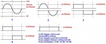
So, getting back to power dissipation on a +/- 36V amplifier with an 8r load.
From post #3:
With 18Vrms, 8R load the power output is 40.5W
Current drawn from the supply is 18Vrms / 8R = 2.25A
I get a power drawn from the supply at 81W (72 * 2.25 / 2)
Power dissipation is 81W - 40.5W = 40.5W
I learned that max power dissipation was at 50% of maximum theoretical output:
Max power diss = Vps*Vps / (16 * RL)
(Both are calculating for class B...Quiescent current for class A or AB adds additional power dissipation)
See jpg
Attachments
Dug,
Your spreadsheet approach will get you the right answer if you set up the problem correctly.
Assume 1 Hertz to make things easy, then each degree represents 1/360 of one second. Calculate the energy delivered by the power supply. That is Vps*Ips*1/360.
Sum up all the energy taken from the power supplies, and divide by the total time. In this case, it's 1 second, so the division is trivial.
If you're careful with your factors and definitions, you'll come up to the result in my white paper.
All the best...
Dan
Working out the power dissipation of an output class AB transistor is quite complex.
At zero volts it is zero.
It then rises to a peak half way up the sine wave then goes down again as the voltage approaches B+.
Then each push pull transistor conducts for half of the sine wave.
At full power in class AB 40% of power is lost in the heatsink and 60% is sent to the speaker.
I did some software for plotting power dissipation and it is worst at 2/3 maximum voltage swing.
All of this is missing one thing: Treating the load as a pure resistance underestimates the actual power dissipation of the transistors.
Well, you learn something every day.
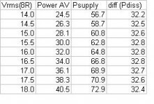
I did as you suggested and came up with the following results. (see jpg)
"...Sum up all the energy taken from the power supplies, and divide by the total time...."
(copy and paste values of the spreadsheet results).
Max power at 32.8W
Now the question is:
Where is the flaw in my "method"?
Is the rms current in the load not the same as the rms current seen by the supply?
I thought about it...
I think I have the answer that satisfies both methods!!
Your method assumes that a sine wave is the signal.
I will now agree to that.
However.
Worst case would be my method with a square wave at half of the supply voltage.
I guess my designs have been a little overkill on the heatsink end.
Well, you learn something every day.
🙂
Attachments
Yes, both methods assume class B and a resistive load.
And yes, class AB (or A) and reactive loads get much more complicated.
We were both trying to provide a starting point.
🙂
And yes, class AB (or A) and reactive loads get much more complicated.
We were both trying to provide a starting point.
🙂
If the load is an ideal inductor or capacitor, all the power goes to the output transisitors and none is dissipated by the load. In any case, if you know the load current, you can calculate the supply current, multiply by the rail volltage and subtract the actual power of the load to get the output device(s) dissipation.
The average value of a rectified sine wave is 0.636 times the peak value, not 0.707 was widely thought. I'm not sure exactly where this comes from, but I have verified it through experimentation. It would seem that the average of a unit sine wave from zero to 180 degrees is 2/Pi. I'd be interested to see the derivation of this. (Remember, don't drink and derive!)
0.707 is the square root of the average of the squares of a sine wave, (Root of the Mean of the Squares) That's not the same as the average of the unsquared values.
If an ideal class B power amplifier is supplying a 10 Amp peak to peak sinewave to a load (100 Wrms@8ohm resistive load), the supply current from each rail is 1.59 Amps.
well if we talk about amplifiers depends also on the efficiency ..rule of thump for class AB will say one pair is capable of 50-60W under 35 volt rails and load of 8 ohms and almost double in 4 if the circuit will allow that and the power supply is stiff enough .
This the optimistic approach and will take through the safe way ...more calculations most of them depend on the SOA of the specific transistor will be required in case of higher rails or more transistors .
There is also other alternatives like the implementation of proper and effective VI limiter which will allow just a 2 pairs of transistors to be supplied with 70+70 ore more volts which will mean that the amplifier will benefit from the high rail voltage and gain in headroom in low levels , measure properly under resistive load at 1KHZ sine wave on bench tests , and in real life and real load at moderate or high levels expect the VI limiter to kick in and start chopping off your dynamic peaks .
so beyond maths the use and the target is very important for proper calculations ...
The second way will play better in low levels eventhough is not what i hi end diyer will like to have as a system ...
Kind regards
Sakis
- Status
- Not open for further replies.
- Home
- Amplifiers
- Solid State
- how to calculate power of an output transistor