Hello everyone,
I have 4 diodes creating a full wave bridge, and am replacing some old diodes that I have been told look they are getting a little hot.
They work for a DC heater on 211 valves. The heater is at 10.5AC and 10V, 3.25A after rectification.
Is there any way to look at Diode specification sheets and determine temp performance, they are DO-247 format.
Rich
Never use "any" diode for large current, such as transmitter tube filament.
Heating (due to the unknown forward voltage drop and filament current), arisen noise level may occur.
For 211 filament I only use 10-16A low voltage drop, fast Schottky diodes (I like MBR series, MBR1045, MBR1645 etc.).
For example MBR1045 has about 0.45V voltage drop at -about- (constant, worst case) 4A (at 25 °C), so it dissipates 1.8W.
The datasheet show for this TO220 device 2 °C/W thermal resistance, so the junction heating up 3.6 °C over ambient temperature.
At about (or over) 3-4A I always use small heatsink for diodes.

Thanks for this, my equivalent calculation is 3.2 °C at 4A so I should be good I guess.
I can also look at some heatsinks, if the seem to get hot, i will run a test for the DC circuit off the amplifier with a 3R 50W resistor and see how they get on.
Rich
I can also look at some heatsinks, if the seem to get hot, i will run a test for the DC circuit off the amplifier with a 3R 50W resistor and see how they get on.
Rich
Are those thermal resistance specifications junction to tab or junction to ambient? The numbers quoted sound like junction to tab to me. Junction to ambient without a heat sink would be much higher.
I generally use bridge rectifiiers bolted to the chassis for high filament current applications like GM70, 211, 845, etc. Devices in T0-220 or TO-247 packages are highly suitable if they are mounted on a small heat sink.
I generally use bridge rectifiiers bolted to the chassis for high filament current applications like GM70, 211, 845, etc. Devices in T0-220 or TO-247 packages are highly suitable if they are mounted on a small heat sink.
The thermal resistance always "junction to case" at infinite heatsink.
Sample:
Up -about- 2W dissipation such small plate TO220 heatsink has 27°C/W thermal resistance.
In this case the whole thermal resistance about 2+27 °C/W (if no insulator, thermal paste).
1.8W on 29 °C/W thermal resistance produces 52.2 °C junction heating up, so junction (if the ambient temperature was 25 °C) will be 77.2 °C.
It's below the "normal" operating conditions for these rectifiers.
For such high currents I would use an active ideal diode bridge based on mosfets: no voltage drop, no heat generated.
Most are based on the LT4320, but there are also other designs.
Most are based on the LT4320, but there are also other designs.
Hey so can I measure the hum on my cathode while it's powered with the existing DC heater with a scope? across the heater terminals (50V and 60V)
This screams for LT4320. Expensive but worth the money. Uforward expressed in tens of mV.
Drawback would be the higher output voltage but maybe a lower voltage filament winding is available? Or in the case of a dedicated filament transformer that one could be replaced.
Drawback would be the higher output voltage but maybe a lower voltage filament winding is available? Or in the case of a dedicated filament transformer that one could be replaced.
Last edited:
I measured my existing set up that has been in for 25 years, and to the 'touch' the diodes used were not very hot.
AC in 10.79 V
DC out 9.95 V
I am not sure what the Diodes are, I don't know if this is possible by looking closely at them?
Rich
AC in 10.79 V
DC out 9.95 V
I am not sure what the Diodes are, I don't know if this is possible by looking closely at them?
Rich
Attachments
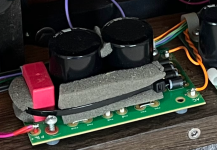
The diodes are on the right where AC is written. How can you say they are cool when you don’t know where they are?
I asked WHAT they were (model number etc if it was easy to understand by looking with more experienced eyes), not WHERE they were! 🙂
Ok. Normally there is either a text or a code on them. You have it in front of you and can focus or look with a magnifying glass. We can't unless you send the device over. They look like 5A10 ... 10A10 or similar types.
Maybe it is because English is not my native language but if you replace them as they look like they have been hot and at the same time you say they are cool that seems contradictory. With 3.25A load current they should be warm to hot. Logic says they must be hot with that current. Also: if they look like they have been hot they likely have been hot. Now person A thinks 45 degrees is hot and person B thinks 60 degrees is hot so normally temperature is measured. Let's keep it simple and see it as a fact that they have become hot. You would do a good job with diodes with lower Uf so Schottky diodes as these will be cooler but then the voltage goes up which is detrimental to the filaments. Dilemma!
What to do?
1. You could investigate if it has multiple filament windings on the power transformer or a separate filament transformer. Then further complex scenarios may be possible.
2. If you don't want any risk of changing multiple things, diminishing resale value and other possible horror you best replace the diodes by exactly the same diodes (which BTW are not DO-247) but now fresh new ones. Better hot diodes again the next years than defective tubes.
3. With the choice for exactly the same diodes you should definitely mount them at a large distance from the PCB. Let's say 6 mm distance from the diodes (body) lowest point to the PCB. Beforehand you could drill 6 mm ventilation holes right below the diodes position to also allow for some air flow from underneath. Costs nothing but delivers. Carefully check if there are no PCB tracks and deburr the holes with an old 10 mm drill.
Last edited:
Deburr by turning the drill between a finger and a thumb not with a machine. BTW the diodes seem DO-27 case types or even larger.
Thanks, I am going to replace the PCB and hard wire so no problem with some air around them, I am not worried about any warranty this was one-off unit, made at the time (not by me) with repurposed PCBs in some locations. This DC heater coming from a 300B designed unit.
I only know the Do-247diodes I was considering to use got VERY hot with Vf 1.45V on a test bench with 10V 3Ohms and these below seemed to be just warm when on, not too hot to touch in the amplifier.
If the diodes produce a higher DC voltage then I can just reduce this with a larger resistor than the R85 currently used (which also gets hot!)
I would not gamble but change the parts for the same but at a higher distance so the device is ready for another 25 years.
Don’t know what R85 is but I take it is a dropping resistor? If it needs to drop more you did not gain much with regards to heat. It was asked if other filament windings/taps are there which no living soul can know but you as the device is a one off in front of you. The only way to less dissipation is Schottky diodes/ideal rectifier and lower filament AC voltage.
What are “these diodes”? Please mention type. What were the DO-247 casing diodes type names? It does not sound good when one replaces unknown diodes for randomly chosen diodes. The casings name does not say much. They need to be picked on similar ratings like the original ones have.
There is no defect but diodes will be replaced and PCBs also replaced. Why? Just to do something?
Last edited:
Well I am changing the layout to update the old PS filter caps, and I wanted to move this PCB, and kind of rework it. I had intended to use the diodes I like the sounds of in other power supplies (ultrafast slow recovery) but these are the ones that get super hot with Vf 1.45V, and so I am left with a dilemma. Leave the circuit as it is and move the board or find some similar diodes as the ones I like are not going to work. I had perhaps mistakingly thought the electrolytic caps could all do with a change. (it does pop a bit on start up now sometimes)
It just does not work that way.
You still do not mention exact data like diode type names/numbers which is odd as their relevant parameters seem to be completely ignored. No one can advise without knowing that. They are chosen for the wrong purpose with a wrong outcome so a bad choice for better sounding filaments (!?). The filaments do not need diodes you like but diodes that do this job correctly.
Good luck with the method but if you appreciate a well working device maybe just leave it like it is. There is no dilemma as it works as intended/designed for 25 years.
Last edited:
I use PSUD2 to make sense power supplies, and I have used these for other locations after liking the sound of an ultrafast slow recovery diode in another project https://www.mouser.co.uk/ProductDetail/511-STTH30RQ06WY. They are clearly not appropriate for this application as I am discovering.
I have no idea what these diodes are currently in use, and others having seen the photo have commented that they look like they are getting hot, but as I explained I did not see it like that when I had the amplifier off it's shelf to have a look, and felt them by touch on the diode case, which is a little strange. I agree I would replace these with like for like if I knew what they were when I have to move for the the DC heater supply and can also allow them to receive more air flow.
I have no idea what these diodes are currently in use, and others having seen the photo have commented that they look like they are getting hot, but as I explained I did not see it like that when I had the amplifier off it's shelf to have a look, and felt them by touch on the diode case, which is a little strange. I agree I would replace these with like for like if I knew what they were when I have to move for the the DC heater supply and can also allow them to receive more air flow.
There is a “S” or “5” visible on diode D3. Desolder one to see its type. This should have been the first step before anything else. No one else except you can tell what diodes your device has. Not knowing and still replacing for randomly chosen parts without attention to the both parts’ technical properties is illogical.
The STTH30RQ06WY has an abnormal high maximum Uf. Power is U x I. Simple. Exactly wrong in a desired relevant parameter.
Maybe it is more optimal to trust the design as it did what it is supposed to do and attempts to change it to better with randomly chosen parts was not a success.
The STTH30RQ06WY has an abnormal high maximum Uf. Power is U x I. Simple. Exactly wrong in a desired relevant parameter.
Maybe it is more optimal to trust the design as it did what it is supposed to do and attempts to change it to better with randomly chosen parts was not a success.
Last edited:

- Home
- Amplifiers
- Tubes / Valves
- How to calculate heating of Diodes