Based on the SPL measurements above, the slight underdamped SPL response of the 4-driver system seems to be evident. The response at 48 Hz is about 2dB down from the flat region of the response between 60 Hz and 100 Hz. The impedance curve that was obtained with the box filled with stuffing indicates that there is a lot of extra damping in the system. This will serve to lower the Qtc a little. If your response is around –3dB down at the new system resonance frequency fc with stuffing, then you are close to Qtc = 0.71 value.

In my view you have everything you need to determine Qtc and you only need Re (Loudspeaker DC resistance) and your impedance plot to calculate Qtc. There are different text-book sources that describe the method. One of them is by D'Appolito Testing Loudspeakers, another one is The Loudspeaker Design Cookbook by Vance Dickason. Perhaps you can also find these online since they are long out of print. I myself have never seen a decrease in Qtc of more than 10% with max. stuffing. Here is a short explanation: https://www.wavecor.com/Measuring_driver_Q-values.pdfThanks, that's interesting.
Going back to a comment earlier, directly measuring a system's Q. I'm curious if I have what's needed to do that, and not just derive. Or if its just much easier to measure the driver free air T&S and impedance sweep of the driver in the enclosure and from that derive Q?
Very best,
In my view you have everything you need to determine Qtc and you only need Re (Loudspeaker DC resistance) and your impedance plot to calculate Qtc. There are different text-book sources that describe the method. One of them is by D'Appolito Testing Loudspeakers, another one is The Loudspeaker Design Cookbook by Vance Dickason. Perhaps you can also find these online since they are long out of print. I myself have never seen a decrease in Qtc of more than 10% with max. stuffing. Here is a short explanation: https://www.wavecor.com/Measuring_driver_Q-values.pdf
Hi,
Thanks. I'm trying to follow the logic. It seems easy. But I'm not getting sensible results.
New enclosure with 2 drivers, sealed. Here's the DATS on it:
Using this logic:
Calculating with my values from DATS:
I'm sort of lost with what happened there.
I must have missed something?
Very best,
Your calcation for Qms is off.
Z0 = SQR (8.204 x 43) = 18.71
Qms = (42.66/(53-33)) x SQR(43/8.204) = 4.88
Qes = 4.88 / ((Zmax/Re)-1) = 1.15
Qts = 0.93
The above method is sensitive to errors reading from the graph though. You can check accuracy to check that SQR (F2 x F1) = Fs.
In this case SQR (F2 x F1) = 41.8 Hz. This is close to Fs = 42.66 Hz, so I would say that Qts is as reliable as you can expect from this method.
our calcation for Qms is off.
Z0 = SQR (8.204 x 43) = 18.71
Qms = (42.66/(53-33)) x SQR(43/8.204) = 4.88
Qes = 4.88 / ((Zmax/Re)-1) = 1.15
Qts = 0.93
The above method is sensitive to errors reading from the graph though. You can check accuracy to check that SQR (F2 x F1) = Fs.
In this case SQR (F2 x F1) = 41.8 Hz. This is close to Fs = 42.66 Hz, so I would say that Qts is as reliable as you can expect from this method.
I zoomed in on your tool, and the info you are seeking is right there on the middle right hand side. LOL
Qts = 0.92.
Hi thanks, that was the issue.
Yea, it's measured there, but I wanted to derive it from just the impedance sweep just as a learning point.
Qts is the driver(s) of course. That's two drivers wired in series. I'm not sure if that matters here.
Ultimately though, is this the Qtc of the box? Or is the measured 0.92 Qts just the Q of the drivers?
Very best,
when you run an imp sweep, your measuring equipment has no idea if the driver is being measured alone or in a box.
if you measure the driver alone, that is the drivers Q
if you measure that driver in a box, that is the resultant driver+boxsize Q
if you measure the driver alone, that is the drivers Q
if you measure that driver in a box, that is the resultant driver+boxsize Q
when you run an imp sweep, your measuring equipment has no idea if the driver is being measured alone or in a box.
if you measure the driver alone, that is the drivers Q
if you measure that driver in a box, that is the resultant driver+boxsize Q
Great points, thanks!
Do you think I can derive Qtc (box dampening) from this impedance sweep and driver T&S values?
My enclosure's net internal volume is 2.6 ft^3 and I stuffed it at 1.538 lbs per ft^3 with polyfil. It has 2 drivers wired in series. I have the before & after stuffing impedance graphs if needed. The simulated Qtc was 0.770 in my model. I'm trying to discover what the Qtc is now after stuffing and real world (not just my model) to account for differences in execution relative to the model.
The model (with Qtc = 0.770):
The 2.6 ft^3 net volume sealed enclosure with the two drivers wired in series with no stuffing:
The above but with 1.538 lbs per ft^3 stuffing polyfil, or 4lbs total of poly fil and the resluting changes:
Resulting ground plane measurement differences, stuffed vs unstuffed (blue = stuffed):
I'm trying to discover what my Qtc is now. I think I have the rest figured out here. It's just the Qtc that is still difficult. It's not 0.770 I imagine anymore. But what is it?
Very best,
Last edited:
This part is actually very well (and clearly) described in Small's original papers.Q can be measured directly. It's a more involved process and can give greater precision for when that's needed. Just seeing whether the resonance is shifting and by how much (F and Q are linked), this method can be revealing.
Including how much the change in volume would be.
The closed box formulas say that Fc=Qtc/Qt*Fs
Circling back to this, I'm trying to understand because I'm not getting sensible calculation results.
My new data is in post #28:
https://www.diyaudio.com/community/...-from-measurements.413381/page-2#post-7702905
Fc is the box resonance with the driver, in my case, unstuffed it's 47.54hz and stuffed it's 42.66hz. Right?
Qtc is currently unknown, so I'm trying to solve for this.
Qt is Qts of the drivers, correct? So my measured Qts of the drivers in series together in the box is 0.92
And Fs is the measured Fs of the two drivers, or is it the measured free air Fs of one driver?
Re-arranging the formula we have:
Qtc = Fc(Qt*Fs)
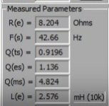
From my DATS (on the stuffed enclosure):
Fc = 42.66hz
Qes = 1.136
Qts = 0.9196
Qms = 4.824
Re = 8.204
Free air of a single driver:
Re = 3.8
Fs = 24.83
Qts = 0.5308
Qes = 0.5896
Qms = 5.317
Vas = 4.147 ft^3
I guess I'm lost in the formula above if I'm using my measured values, versus driver free air values?
Using single driver free air T&S from DATS and the measured box Fc:
Qtc = 42.66hz (0.5308 * 24.83hz)
Qtc = 562.248 (??)
Using the DATS information only from the stuffed box:
Qtc = 42.66hz (0.9196 * 24.83hz)
Qtc = 974.084 (??)
Now, before, someone mentioned just using Qes instead of Qts:
Qtc = 42.66hz (Qes * Fs)
Qtc = 42.66hz (0.5896 * 24.83hz)
Qtc = 624.532 (??)
I'm confused how you calculated Qtc 0.71 in the original few posts from my values with this formula.
Do you think you could break it down? Maybe I'm confusing values because Fs, Fc, Qt vs Qt____ something just get flopped around too much?
Very best,
If I had a program displaying all the values needed, I wouldn't try repeating calculating everything by hand. Just stuff the box until you get a Qtc you like.Hi thanks, that was the issue.
Yea, it's measured there, but I wanted to derive it from just the impedance sweep just as a learning point.
Qts is the driver(s) of course. That's two drivers wired in series. I'm not sure if that matters here.
Ultimately though, is this the Qtc of the box? Or is the measured 0.92 Qts just the Q of the drivers?
Very best,
With 2 drivers in one enclosure, Vas doubles and Re changes to either double (=series connection), or halves (= parallel connection). Qts of both drivers as a system is the same as the single one.
Qtc is the Q of the box, as you've measured the drivers in their enclosure. Qts is the free air Q of the driver.
If I had a program displaying all the values needed, I wouldn't try repeating calculating everything by hand. Just stuff the box until you get a Qtc you like.
With 2 drivers in one enclosure, Vas doubles and Re changes to either double (=series connection), or halves (= parallel connection). Qts of both drivers as a system is the same as the single one.
Qtc is the Q of the box, as you've measured the drivers in their enclosure. Qts is the free air Q of the driver.
Thanks, part of this is to simply understand it, so not just trusting a value from a program, but rather knowing how to get there. That's the point of doing it by measurement and hand, to understand better.
You say stuff the box to get a Qtc, but... that's the point, to find out Qtc.
Thanks - that's helpful to know that Vas doubles and Re changes (I measured this change). I couldn't measure Vas on its own with the drivers installed, so just doubling the worst measured driver might make sense and use that. Knowing the Qts of the drivers in the system is the same as a single free air driver (I assume) is helpful for calculating. I'll try and verify.
Qts is verified and measured. I'm good there.
Qtc is not however. I can't seem to get the measurement/calc from my information here. Everything up to this point is cryptic or doesn't result in a sensible calculation. Hence my asking.
Thanks so far.
===================================
Qtc = Fc(Qt*Fs)
If QTs is the driver in free air as you mentioned
Fs is the driver in free air
Fc is the resonance of the drivers in the enclosure (42.66hz measured)
Then:
Qtc = 42.66hz (0.57 * 22hz)
Qtc = 534.956 or 0.535
But this doesn't really make sense. Does it?
Very best,
Last edited:
I guess I'm lost in the formula above if I'm using my measured values, versus driver free air values?
For box calculations, you need to use the values you found with the speakers mounted in their enclosure. Don't mix them with free air values.
Anything with an 's' is free air (fs, Qts, Qms, Qes). In box parameters are with a 'c', Fc, Qtc, etc.
The interrelation is: Qtc = Qts x SQR ( alpha + 1), and Fc = fs x SQR (alpha + 1), where alpha = Vas / Vb.
Perhaps the confusion comes from your impedance plot program, as it shows all values with an 's', as it doesn't know whether you've just measured your speaker free air or in-box.
You would really like this Loudspeaker Design Cookbook I mentioned, as it dives into all the issues you are touching.
Qtc is not however. I can't seem to get the measurement/calc from my information here. Everything up to this point is cryptic or doesn't result in a sensible calculation. Hence my asking.
You can use the same 'Wavecor method' for both free air and inbox calculations using the correct impedance plot, free air plot for Qts, in-box plot for Qtc.
Vas is a difficult to determine parameter, hence using the impedance plot of the driver in its enclosure is a workaround where you don't need to know Vas.
I don't understand the whole further discussion, Small clearly shows what calculations and measurements must be done? (see my previous post)
Just simply follow that, there isn't anything more to it.
Just simply follow that, there isn't anything more to it.
For box calculations, you need to use the values you found with the speakers mounted in their enclosure. Don't mix them with free air values.
Anything with an 's' is free air (fs, Qts, Qms, Qes). In box parameters are with a 'c', Fc, Qtc, etc.
The interrelation is: Qtc = Qts x SQR ( alpha + 1), and Fc = fs x SQR (alpha + 1), where alpha = Vas / Vb.
Perhaps the confusion comes from your impedance plot program, as it shows all values with an 's', as it doesn't know whether you've just measured your speaker free air or in-box.
You would really like this Loudspeaker Design Cookbook I mentioned, as it dives into all the issues you are touching.
Thanks, that is actually very helpful the differentiate s and c this way. That is now very clear, so thanks.
Yes, its confusing the DATS produces s values in my enclosure measurement.
So in the Qtc = Qts X SQR (alpha + 1)... is that Qts free air or my measured Qts of the drivers in series? This is confusing since we just established s is free air and we don't mix them?
And the Fc = Fs * SQR (alpha +1), is that Fs the measured Fs of the two drivers, or is that the Fs of a single driver in free air since its s?
Alpha = Vas/Vb, I can then calculate this as Vas would be doubled with my two drivers and Vb is the enclosure net volume which I can measure (2.6 ft^3). Correct?
Lastly, I guess I'm now lost on SQR being a new acronym so far in this discussion. Forgive me, what is that?
I'll look up the Cookbook and get it. Thanks.
Very best,
I don't understand the whole further discussion, Small clearly shows what calculations and measurements must be done? (see my previous post)
Just simply follow that, there isn't anything more to it.
Thanks, it just seems more complicated. Lots of assumptions with this as being just 1 driver. My system is two drivers. So its less obvious to me. There are acronyms there I don't recognize and a ratio and table referenced with things I didn't measure. I'll see if I can find them.
Sorry, not trying to be difficult, I'm just a hobbyist trying to understand. Everyone starts somewhere.
Very best,
You can use the same 'Wavecor method' for both free air and inbox calculations using the correct impedance plot, free air plot for Qts, in-box plot for Qtc.
Vas is a difficult to determine parameter, hence using the impedance plot of the driver in its enclosure is a workaround where you don't need to know Vas.
Hrm, I did that above and you corrected it, and the Qts was 0.92. I guess I'm not seeing how this translates to Qtc. The measurements don't calculate to a sensible Qtc value.
The ground plane measurements imply I should have a Qtc that is lower than my simulated Qtc. But, I'd like to calculate it to know, unless its measured here and I'm oblivious to it.
Thanks!
Very best,
My bad, I should have written Qtc, as this was your driver in box (I assume).and the Qts was 0.92. I guess I'm not seeing how this translates to Qtc.
Qts = free air single driver. Double drivers Qts remains the same as for 1.is that Qts free air or my measured Qts of the drivers in series?
Fs of single driver, see previous post.And the Fc = Fs * SQR (alpha +1), is that Fs the measured Fs of the two drivers, or is that the Fs of a single driver in free air since its s?
CorrectAlpha = Vas/Vb, I can then calculate this as Vas would be doubled with my two drivers and Vb is the enclosure net volume which I can measure (2.6 ft^3). Correct?
SQR = Square Root
Acronyms you don't understand?There are acronyms there I don't recognize and a ratio and table referenced with things I didn't measure. I'll see if I can find them.
It's explained even in this little snipped of text.
Qms, Qes and Fs
The rest are just changes in names according to the additional sets of measurements, naming is not very important here.
Followed by a ratio between masses and volumes.
For two drivers, when used in parallel or series and doing exactly the same response, you also measure them as if they were just one speaker.
Just dig up the original papers from Small and Thiele, they are a lot more straightforward I think than having whole debates.
But that is just me 🙂
- Home
- Loudspeakers
- Subwoofers
- How to Calculate Changes in Q from Measurements?