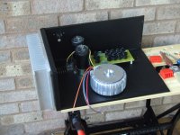
you can try stål.
Out of curiosity, what's the going rate for aluminum in Norway ?
Out of curiosity, what's the going rate for aluminum in Norway ?
are you thinking of the price?
depending on thickness, 5-10USD pr Kg. 3-10mm. "standar" aloy.
Nothing worse than ordering parts
Especially when your a total newb like me, when I go to mouser and search for 10 ohm resistor and get 2000 different options I would like to know that I am getting the right ones.
Hopefully from the help of you guys, and me doing this it will help others and make if easier for folks to just go in and click a link or insert a certain bom, and done.
Now I just need to figure our how to upload the file, as diyaudio.com is telling me that it is a invalid file.
Now I just need to figure our how to upload the file, as diyaudio.com is telling me that it is a invalid file.
Is there a way you can 'save' it at mouser and post the link?
Or maybe make it a google doc, and post that link?
Lets see if this work, if it does I don't know if everything is right. I think I tried to pick metal film resistors. Let me know if there is anything that needs changes. I figured the transistors and other stuff are coming from other vendors, so I will try and do a google doc later and put those on the original bom.
http://www.mouser.com/ProjectManager/ProjectDetail.aspx?AccessID=0cca714c64
http://www.mouser.com/ProjectManager/ProjectDetail.aspx?AccessID=0cca714c64
thinking of the price?
Wondering how you manage to spend $2000 on a monaural amp.
Obviously, it's not the alloy.
Wondering how you manage to spend $2000 on a monaural amp.
Obviously, it's not the alloy.
$2000. wel.
heatsinks: $250
transformer: $200
PSU: $250
softstart: $100
amp parts: $200
15Kg alu: 150
cutting and CNC of alu: $150-200
misc: $200
PCB: $40
and then ther is finnish. (Paint and anodize)
this is pr monoblock.
Last edited:
Magic Smoke
Does anyone have the F5 schematic with the correct measured voltages around the circuit.
I got a little puff of magic smoke out of mine when I first turned it on.
The supply rails are OK, there is no measured output voltage but the initial bias is very high.
Does anyone have the F5 schematic with the correct measured voltages around the circuit.
I got a little puff of magic smoke out of mine when I first turned it on.
The supply rails are OK, there is no measured output voltage but the initial bias is very high.
P1 and P2 is turned the wrong way. measure resistance across the resistors in paralell with the pots. you want to see 0ohm.
that is not the way to start.
start at zero bias but first. you need to find out what burned, and if the part(s) are gone.
start at zero bias but first. you need to find out what burned, and if the part(s) are gone.
If you were a gambling man, what would you say would be most likely to be burnt ?
It was only ON for a few seconds.
Thankfully I only had one amp connected, just to test the PSU.
It was only ON for a few seconds.
Thankfully I only had one amp connected, just to test the PSU.
Last edited:
as this was the first start up, and i don't know nothing about the actual build, i would say it can be anything.
Well, I've just turned both P1 and P2 to ZERO and thought I'd give it a go.
V(R11) and V(R12) are both 0V and output offset is 0V.
Good sign that output devices are not short.
Gently varying P1 I can get the bias up to 0.6V/0.47R = 1.27A with the output offset climbing gently but being held in check with small adjustments on P2.
So I've got 1.27A bias and 0.2mV offset.
I think I might have been lucky. Tomorrow I'll need to let it settle and warm up.
In the 5 minutes that I was playing with it, the heatsink didn't even get above cold.
Attachments
yes it looks like you were Lucky.
you can let it warm up and re-adjust the bias and offset after 30-60min. depending on your sinks.
you can let it warm up and re-adjust the bias and offset after 30-60min. depending on your sinks.
Come to think about it, I think I know where the smoke would have come from.
My bias was set at 2.2/0.47 = 4.68A.
R11 and R12 would have been dissipating 10W each.
That would make them smoke, they were only on very briefly so will have survived.
My bias was set at 2.2/0.47 = 4.68A.
R11 and R12 would have been dissipating 10W each.
That would make them smoke, they were only on very briefly so will have survived.
- Home
- Amplifiers
- Pass Labs
- How to build the F5
