Shorting rail to ground would definitely look pretty exciting, but unless it blew a trace off the board it's unlikely to hurt anything.
Something seems to be limiting base current on Q9. It should be around 125 x gain at that collector current, so it's going to need .1mA base current at least to operate U2. Can you measure the voltage on J3, pin 3 or 4 to digital ground and U1, pin 6 to digital ground? Let's verify the control board is signalling with a good 5V and the optoisolator is turning completely on.
Something seems to be limiting base current on Q9. It should be around 125 x gain at that collector current, so it's going to need .1mA base current at least to operate U2. Can you measure the voltage on J3, pin 3 or 4 to digital ground and U1, pin 6 to digital ground? Let's verify the control board is signalling with a good 5V and the optoisolator is turning completely on.
Jeff,
Thanks for taking the time to figure this out for me.
J3 pin 3/4 to ground 4.96V
U1 pin 6 to ground 3.94V
Thanks for taking the time to figure this out for me.
J3 pin 3/4 to ground 4.96V
U1 pin 6 to ground 3.94V
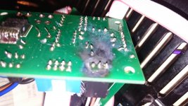
II did the same thing on one of my speaker protect boards. Measuring the rails from the solder side of the board. My wife came in and asked me something. I looked up to answer, the probes slipped and there was big boom and sparks.
Then I had to explain that the hobby is perfectly safe, I have full control and my amps won't catch fire and that this very board is meant to protect them from catching fire. 😛
Everything worked fine after this accident. 😉
Then I had to explain that the hobby is perfectly safe, I have full control and my amps won't catch fire and that this very board is meant to protect them from catching fire. 😛
Everything worked fine after this accident. 😉
Attachments
Jeff,
Thanks for taking the time to figure this out for me.
J3 pin 3/4 to ground 4.96V
U1 pin 6 to ground 3.94V
No problem! This is actually good reference for me. There's obviously some difference in our parts causing some discrepancy here, so this will help with other's assembly.
I've added self resetting fuses in the supplies to feed the rail connection of the control boards with slipping test probes in mind. The unfused connection has always looked like trouble waiting to happen to me.
U1 isn't turning on completely. We better get the high voltage side sorted out first. What is your current flow through R8 now?
Being a compulsive person I just can't let this be until it works. I am going to put one more speaker protect board together.
yngvejos, could you look at the attached schematic and confirm these are the part values you used?
Jeff, after i put this one together if I get the same results would it be OK to mail the board to you. I imagine remote diagnosing is both difficult and annoying for you.
Thanks,
Evan
yngvejos, could you look at the attached schematic and confirm these are the part values you used?
Jeff, after i put this one together if I get the same results would it be OK to mail the board to you. I imagine remote diagnosing is both difficult and annoying for you.
Thanks,
Evan
Attachments
I don't mind diagnosing this in the forum. This is helpful for anyone else running into issues. We just need to verify some current flows. If all control circuits are going to maintain steady operation as is with no excessive heating, you can just drop the value of R9 to match.
For R9 on my existing board when I lowered the resistance to increase the current I found that although the current increased a bit the voltage also dropped.
R9 430R 2.4V 5.58mA
R9 186R 1.6V 8.6mA
I can put together another board (they don't use many parts) to verify it operates the same.
R9 430R 2.4V 5.58mA
R9 186R 1.6V 8.6mA
I can put together another board (they don't use many parts) to verify it operates the same.
Being a compulsive person I just can't let this be until it works. I am going to put one more speaker protect board together.
yngvejos, could you look at the attached schematic and confirm these are the part values you used?
Jeff, after i put this one together if I get the same results would it be OK to mail the board to you. I imagine remote diagnosing is both difficult and annoying for you.
Thanks,
Evan
They seems familiar. I used the values from Jwilhelms bom, worked fine with 60v rails. Haven't measured currents to check that everything is operating correct though. Just did the heat check with my finger and tested all functions.
Thanks yngvejos
OK with
R9 100r .85V 8.5mA
R11 6k8 .36V .05mA
R7 2k2 58V 26mA
R8 430R 9.2V 21mA
U1 pin 6 to digital GND 3.95V
U1 pin 1 to amps ground 2.9V
J3 pins 3,4 4.95V
Lowering the resistance of R9 from 186R to 100R did not increase current flow.
OK with
R9 100r .85V 8.5mA
R11 6k8 .36V .05mA
R7 2k2 58V 26mA
R8 430R 9.2V 21mA
U1 pin 6 to digital GND 3.95V
U1 pin 1 to amps ground 2.9V
J3 pins 3,4 4.95V
Lowering the resistance of R9 from 186R to 100R did not increase current flow.
Of note. I put together another protect board. some Semiconductors from different lots.
This one gives a DC fault 8 out of ten startups. On one of the startups where it held I measured voltages. They seem similar to the one that works except for R9 andR11
R9 100R .78V 7.8mA down from 8.5mA
R11 6K8 .27V .04mA down from .05mA
I did check for DC at the amps output. It's around 2mV
This one gives a DC fault 8 out of ten startups. On one of the startups where it held I measured voltages. They seem similar to the one that works except for R9 andR11
R9 100R .78V 7.8mA down from 8.5mA
R11 6K8 .27V .04mA down from .05mA
I did check for DC at the amps output. It's around 2mV
I'm away from a computer until later this evening, but false triggering is a sign of a cold solder joint. Rail voltage is intermittent.
Reflowed all the joints and checked around with an ohm meter. Also rechecked wires for rail voltage hook up. Same result. I increased the delay between the amp coming on and the speaker connecting and now this board works. Voltage as best I can measure was .5V when the board was tripping. It is still sensitive, When I turned on the rest of the amps this one trips.
Hi Valery,
No the dc detect/speaker protection board is having some issues. I have a few of these running and they seem to work but when I check current flow the numbers seem a bit off. The latest one seems very sensitive to dc offset. That is the fault that shows.
No the dc detect/speaker protection board is having some issues. I have a few of these running and they seem to work but when I check current flow the numbers seem a bit off. The latest one seems very sensitive to dc offset. That is the fault that shows.
There's a pull down resistor that Valery suggested I add to the DC detection circuit. I'll post it later.
I've added a 470k resistor to from base to emitter on Q4 on newer versions of the protection system. If you have a 1205 SMT version, you can solder one right on the pads of the transistor.
I'm going to do some breadboard testing in the morning, and see if I can figure out why you aren't getting higher current flow. I think it's because U1 isn't turning fully on. I'll know better after some more live testing.
I'm going to do some breadboard testing in the morning, and see if I can figure out why you aren't getting higher current flow. I think it's because U1 isn't turning fully on. I'll know better after some more live testing.
Don't want you guys to think I'm waiting to be hand fed answers....I have been trying to understand how/why the optoisolator is hooked up the way it is. It is getting proper current and voltage at it's input vf1 vf2. 2.84V or 1.4V per channel and 21mA current. Vcc is 11.94V I am not sure about the hookup of Vo1. 11.8 volts is applied o this pin through r10. About 1mA.
Looking at U2 the mosfet driver it wants minimum 3 up to 30 mA current to turn on. It is getting around 8mA. low but enough to turn on.
Just me trying to understand...
Looking at U2 the mosfet driver it wants minimum 3 up to 30 mA current to turn on. It is getting around 8mA. low but enough to turn on.
Just me trying to understand...
I reread the datasheet for U1. It looks like I confused input and output currents. It is meant to only sink 8mA continuously max. Mine passed much more current in testing, but it's above the published maximum specs. I'm going to do some testing and see if I can make the circuit work properly at that low current level. I chose that optocoupler to keep the number of different parts needed down, but there are other options that will sink higher current.
- Home
- Amplifiers
- Solid State
- How to build a 21st century protection board