Yes, I think, as they work in a purely switching mode, having rather low voltage drop - heat is not going to be a problem...
I've got components coming tomorrow. I think I'll hand etch one to torture before I order boards.

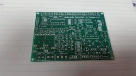
New boards arrived. I haven't worked up enough energy to hand etch any mosfet relay boards to test yet. I think I'll just add some extra board to the top and get some done. I can shear them down later if space is an issue.
How do you program this one ? (usb ? software ?) 😕
OS
How do you program this one ? (usb ? software ?) 😕
OS
Pull the IC and plug it into an Arduino Uno.
Pull the IC and plug it into an Arduino Uno.
That's a little proprietary. 😀 Ohhh .. UNO is the development board , does not
use the "facist" FTDI chip ( Atmega 16U2 instead). 😎
OS
Uno's are great units. I give them to kids all the time. The Atmega IC is available with the Arduino bootloader already on it or it can be loaded from the Uno. It should work well as long as I didn't screw up the clock circuit.
My control board.
I've done 1 change - used the "heating" output ... replace or combine
digitalWrite(HeatingOn, HIGH); with digitalWrite(SpeakersOn, HIGH);
Get rid of "SpeakersOn" and just the heating output switches high at the end of
the "main loop".
You could cleanup and rename/eliminate all the "tube stuff" (if you are not using them).
your "heatingON" could switch bigger relays or SS relays.
change 2 - use pin 15 / (D12) for a full dual color fault led setup (common anode
red/green). Just assign "powerLED2" to pin 15 , replace any fault indication with
led2 - red !!! I would also need to add a resistor/diode in series with the new red.
Easier to know whether you "screwed up" with colors. 😀
OS
New boards arrived. I haven't worked up enough energy to hand etch any mosfet relay boards to test yet. I think I'll just add some extra board to the top and get some done. I can shear them down later if space is an issue.
Eye candy 🙂
I've done 1 change - used the "heating" output ... replace or combine
digitalWrite(HeatingOn, HIGH); with digitalWrite(SpeakersOn, HIGH);
Get rid of "SpeakersOn" and just the heating output switches high at the end of
the "main loop".
You could cleanup and rename/eliminate all the "tube stuff" (if you are not using them).
your "heatingON" could switch bigger relays or SS relays.
change 2 - use pin 15 / (D12) for a full dual color fault led setup (common anode
red/green). Just assign "powerLED2" to pin 15 , replace any fault indication with
led2 - red !!! I would also need to add a resistor/diode in series with the new red.
Easier to know whether you "screwed up" with colors. 😀
OS
Cool stuff. The "platform" gives a lot of freedom. No limits for ideas 😉
Cool stuff. The "platform" gives a lot of freedom. No limits for ideas 😉
Actually , If Jwilhelm can replace those relays with FETS , I could do a lot less
modifications and just use the "heatingon" for my dual color setup.
Since my "big baby" amp is wired around this control board , less is best. 😎
The scheme of the "main loop" is now quite apparent. Almost at the point of
writing new stuff. Your commented script was quite helpful.
OS
Speaking of "less is best", a single LED can be flashed in different patterns to indicate the fault type. Add PWM to the LED and the fault may even seem attractive 😉Actually , If Jwilhelm can replace those relays with FETS , I could do a lot less
modifications and just use the "heatingon" for my dual color setup.
Since my "big baby" amp is wired around this control board , less is best. 😎
The scheme of the "main loop" is now quite apparent. Almost at the point of
writing new stuff. Your commented script was quite helpful.
OS
Speaking of "less is best", a single LED can be flashed in different patterns to indicate the fault type. Add PWM to the LED and the fault may even seem attractive 😉
That's how it is now.
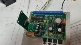
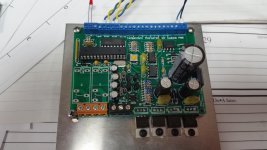
My new condensed version with a mosfet relay.
Are you going to share a schematic? I sure hope you do. How many watts will this circuit handle? Very nice layout too.😀
The protection board itself is up and running. I've got the wrong Mosfet driver on the relay I should have testers ready next week.
My new condensed version with a mosfet relay.
Nice. Real nice.
I anticipated you changing the board layout considerably and rewired my big
amp with lot's of extra wire length for the controller. I have a 1A 15V trafo , too.
Glad to see you kept the tube heater output , that is my fault led output now
(bright red flash)... see everything from across the room.
I'm going to explore the analog/reference part of the chip(atmega) next , this could
really be interesting.
OS
Are you going to share a schematic? I sure hope you do. How many watts will this circuit handle? Very nice layout too.😀
I'm having trouble uploading the schematics. I'll try again later. I think this will handle just about anything you hook to it. The mosfets in the speaker relays are rated for 100 volts 180 amps.
Nice. Real nice.
I anticipated you changing the board layout considerably and rewired my big
amp with lot's of extra wire length for the controller. I have a 1A 15V trafo , too.
Glad to see you kept the tube heater output , that is my fault led output now
(bright red flash)... see everything from across the room.
I'm going to explore the analog/reference part of the chip(atmega) next , this could
really be interesting.
OS
I added a couple extra outputs for future use as well. I didn't connect any of the analogue inputs though.
- Home
- Amplifiers
- Solid State
- How to build a 21st century protection board