Even if you have perfect AC signal balance from the Phase Inverter it still may not be balanced after the output stage with the variance in gm in the power tubes.... Global negative feedback provides the error correction to keep things in balance...provided there is enough built in allowance of dB headroom Gain for this feedback correction...
Thank you so much for reposting this. Truly classic, from Usenet days, at least. I'd lost my copy but have tried to describe it to several people over the years.Best regards!
Much thanks,
Chris
Let's say in a cathodyne you replace the plate resistor with a potentiometer, using a value matching the cathode resistor. Wide open; normal cathodyne phase splitter. Closed, cathodyne plate connects to B+ and no audio signal to 1 output tube. This tube then just sits conducting its bias current, while the other drives signal into the output transformer.
Does this give linear control over 2nd harmonic cancellation? I.e., control from p-p to single ended? For small signal levels, at least? Thanks!
Does this give linear control over 2nd harmonic cancellation? I.e., control from p-p to single ended? For small signal levels, at least? Thanks!
Some attention needs to be put on the proper setting of the anode voltage of preceeding stage. Considering a direct galvanic connection from preceeding anode, she has a strong say in terms of the splitters grid voltage. And hence - cathode voltage. And overall balance.
Schematic didn't show up
It might be noted that R24 and R25 ought to be fairly well matched too, as they are in parallel¹ with the cathodyne inverter RK and RA resistors … which you spec at 1% or better.
Just saying,
GoatGuy ✓
¹ … well, not exactly, but certainly electrically from an AC load perspective. 1/(¹⁄₈₀ ⊕ ¹⁄₃₃) = 23.4 kΩ
When someone is selling a solution to a problem, they have to convince you that you have the problem.
I have a spare frame _and_ a spot on the wall for this quote. Love it!
Attachments

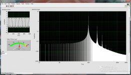
I finally got some analysis of my cathodyne unbalancing potentiometer. 1st frequency plot shows balanced position of the pot - 3rd harmonic is dominant. Second shows unbalanced - 2nd harmonic dominant. Third shows further unbalancing. So I can get 3 different harmonic responses within the pots range.
Attachments


Last edited:
Screen plots 1 and 2:
Not only is the 2nd harmonic dominant in the unbalanced condition, that 2nd harmonic is Much Larger than the 3rd harmonic was in the balanced condition.
Balanced = Lower THD.
Unbalanced = Higher THD.
Not only is the 2nd harmonic dominant in the unbalanced condition, that 2nd harmonic is Much Larger than the 3rd harmonic was in the balanced condition.
Balanced = Lower THD.
Unbalanced = Higher THD.
So the basic idea is to change the THD character of the amplifier at will. Of course, the perfectly balanced position (2nd harmonic nulled) is best - measurement wise. And - so they say - the predominance of even harmonic distortion gives a desirable sonic character, of course in that "measures lousy, sounds great" phenomena that we all know exists somehow in the realm of amplifiers and speakers.
Can these settings persist with regard to tube ageing, temperature changes and all other considerable factors? I dunno!?
Can one make the sonic character change as a function of frequency, i.e. have a smooth shift from perfectly balanced to unbalanced (rising 2nd harmonic content with frequency)? I bet you can.
Of course, the gain of the amplifier changes as you unbalance the cathodyne - I compensated for that when I made the plots by increasing the drive. The simple unbalancing potentiometer has consequences... But it works.
All I did was replace the 100K plate resistor with a 100K potentiometer. I guess I got lucky that the 2nd harmonic null was within range, i.e. just off the far end stop. With the pot all the way closed (or part way closed), the cathode side of the phase splitter is doing all of the driving to the one output tube remaining fully functional.
Last edited:
You can use the 2nd and 3rd harmonic mix that sounds best. However, if you set the amp for second harmonic distortion by un-balancing the drive to the output tubes, you will get non-symmetrical damping.
Another factor you probably did not think of:
Connecting a loudspeaker one way, and then reversing the phase results in the following: The loudspeaker has its own 2nd harmonic distortion. Connected one way the 2nd harmonic of the loudspeaker and amp adds. Connected the other way, the 2nd harmonic of the loudspeaker and amp partially cancels.
If you want more 2nd harmonic at high frequencies, put a small capacitor across the plate load resistor of the concertina. At high frequencies, the plate signal will be lower than the cathode signal. Or, put a capacitor across the cathode resistor. At high frequencies, the cathode signal will be lower than the plate signal. Take care not to use too much capacitance you use, or you will be unbalancing the bass frequencies as well as the mid and high frequencies. Of course the cap will cause a time lag of that signal, so may, and probably, will get some upper order harmonics too.
If you want to experiment with dominant 2nd harmonic distortion, why not try some tried and true single ended amps?
No need to deliberately dis-balance amps if you want better sound. Instead, design an amp that is not especially balanced. Concertina is perfectly self-balanced if anode and cathode see the same load by both AC and DC.
Just don't use LTP input stage for the sake of balance, and yua'll be happy. SE is the best way to go in terms of sound quality, but if your speakers have not enough sensitivity, you may go with PP. Adding distortions do not improve sound. You want as less them as possible, but not by artificial ways like making the amp overall symmetric.
Just don't use LTP input stage for the sake of balance, and yua'll be happy. SE is the best way to go in terms of sound quality, but if your speakers have not enough sensitivity, you may go with PP. Adding distortions do not improve sound. You want as less them as possible, but not by artificial ways like making the amp overall symmetric.
Thanks for that misinformation, because that's wrong. Every high quality amplifier like Fisher, Scott, etc., uses an adjustable pot in the cathode circuit. Now go tell those successful, professional, audio manufacturers that they're wrong.You balance by the plate resistor adjustment, and not from the cathode.
Successful manufacturers are often wrong, by the way. They just offered some production in right time to right market. Altec Lansing, RCA, Philips, for example, had much better designs than Fisher and Scott, just their markets were different.Thanks for that misinformation, because that's wrong. Every high quality amplifier like Fisher, Scott, etc., uses an adjustable pot in the cathode circuit. Now go tell those successful, professional, audio manufacturers that they're wrong.
...and you are both wrong. 🙂
A first, it does not matter which resistor to adjust, in cathode or anode. And there is absolutely no pint in adjusting them. Just make them equal, make grid leak resistors of the output stage equal, and run them way below sensible grid current.
Last edited:
Being a long-time service tech, it DOES matter, sorry to say you're another "wrong" one. It matters in designing a safe product, something that perhaps you're not aware of....and you are both wrong. 🙂 A first, it does not matter which resistor to adjust, in cathode or anode. And there is absolutely no pint in adjusting them. Just make them equal, make grid leak resistors of the output stage equal, and run them way below sensible grid current.
Handling high voltages inherent in tube amplification is nothing to ignore, either in design, or later on for "adjustment purposes". That is why, per good design practice, along with adhering to electrical codes, an adjustment for something like phase splitter "tuning" is at the cathode end of things. Because using such a control at the lower voltages in the cathode circuit is much smarter and safer than putting it up where the higher, and more dangerous B+ is on the plate. This also follows along with measuring output tube biasing voltages - you'll see notes discussing the adding of a small value resistor to the cathode, for measuring purposes.
And yes, some manufacturers made "better" products than others, that's true even today, but why even bring that up unless you're biased towards certain ones. We're not discussing any particular manufacturer here, I assume, other than giving examples. In the later RCA Victor designs, for example, they added an additional 22K resistor from the cathode to the output grid going to the bottom 6BQ5 only.
The bottom line is about proper, safe design.
Thanks for that misinformation, because that's wrong. Every high quality amplifier like Fisher, Scott, etc., uses an adjustable pot in the cathode circuit. Now go tell those successful, professional, audio manufacturers that they're wrong.
No. If you change the cathode resistor with a pot, you'll change the bias operating point, as essentially you're changing the cathode resistor.
The best way is to do it by the plate, in this case a 80K resistor followed by a 50K pot would do it.
Wrong again sir, sorry. In "proper" design of a cathodyne splitter, the biasing of the tube is taken from the top of the cathode resistor, not the ground end as you apparently think. Do a little research of known (commercial) circuits, and you'll soon understand the workings better.
This, of course, only applies to cathodynes that are capacitor-coupled to the previous stage, which is what I contend we are discussing here.
This, of course, only applies to cathodynes that are capacitor-coupled to the previous stage, which is what I contend we are discussing here.
Last edited:
>>The best way is to do it by the plate, in this case a 80K resistor followed by a 50K pot would do it.
Darn. I already have a pack of 100K linear dual pots on hand. I'll see if I can get them to work; i.e. identifyable, repeatable setting positions for 2nd null, 2nd pronounced. That might be a while!
Darn. I already have a pack of 100K linear dual pots on hand. I'll see if I can get them to work; i.e. identifyable, repeatable setting positions for 2nd null, 2nd pronounced. That might be a while!
- Status
- Not open for further replies.
- Home
- Amplifiers
- Tubes / Valves
- How to balance a Cathodyne phase splitter?