The kicker is the amplifier uses fixed resistances for the plate and cathode resistors; the balance must be "close enough" across the range of resistor tolerances. What if I'd like to dial it in closer to perfect?
If I were to move the plate voltage of the preceding stage higher or lower, relative to the B+ feeding this cathodyne stage, would that move the amplitude balance between the tubes plate and cathode outputs more in line at some point?
Or, does positioning the grid voltage @ 33% of B+, say 100V, provide the greatest dynamic range for this circuit? Aaand, make that 50% or 20% of B+; all that happens is one side or the other of the tube runs out of signal swing latitude - no change in gain between the plate and cathode outputs.
Is there a standard adjustment circuit for one of these using ordinary 100K fixed plate and cathode resistors? Use a 91K with a 20K potentiometer in the cathode leg?
Thanks for any help / discussion
use , say, 100k plate resistor plus 91k + 20k trimmer cathode to ground (for relative safety), that should be more than enough.
Correct.Aaand, make that 50% or 20% of B+; all that happens is one side or the other of the tube runs out of signal swing latitude - no change in gain between the plate and cathode outputs.
There is no good reason to aim for 'perfection' here, unless you have a perfect output stage with exactly equal gain in both halves and a perfect OPT.
There is at least one good reason not to aim for perfection: an adjustable resistor introduces a possible point of failure so reduces reliability.
There is at least one good reason not to aim for perfection: an adjustable resistor introduces a possible point of failure so reduces reliability.
Assuming this is direct coupled to the previous stage, one trick is to use a partially bypassed resistor divider to set the grid bias of the cathodyne without having to compromise on the OP of the stage driving it.
Example here PS-4 & PS-5 Tube Power Supplies
Example here PS-4 & PS-5 Tube Power Supplies
A Cathodyne is balanced per se if the cathode and plate resistors plus the load impedances in parallel with them are equal. It's best operating point appears to be when the voltage drop over the tube is half the supply voltage.
Best regards!
Best regards!
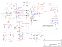
Here is my cathodyne circuit. I just picked through 10 33k resistors and picked the closest matching pairs. Started with a 12au7 as the cathodyne but the 6CG7 had lower measured distortion for me. Yes ~50% voltage drop over the cathodyne tube seems to be the sweet spot. With this circuit it is easy to play around with the voltage drop over the tube by playing with the grid resistors.
Attachments
Looking at your circuit diagram I have a question:
The voltage gain from input splitter circuit to anode differ from the voltage gain from the input splitter to the cathode circuit isn't it?
The voltage gain from input splitter circuit to anode differ from the voltage gain from the input splitter to the cathode circuit isn't it?
JoeAlders,
Huh?
Unless there is significant capacitive currents from the grid to the cathode and grid to the plate, and significant capacitive current from the cathode to the filament, or you have a gassy tube, then . . .
The cathode current and plate current are exactly the same. The same current change in identical cathode resistors and plate resistors has exactly the same voltage change, only the direction changes. The gain of the cathode, and the gain of the plate are less than unity.
I believe this is an old argument. Perhaps I never understood the real outcome. Personally, I do not use that kind of invertor. I prefer using a triode pair, with a current sink in the cathode circuit (not a current source, a current sink). A tradeoff of that is that gain can never exceed u/2; but I like that topology anyway. When I use a current source, it is in the plate of a single triode stage, but that is not a push pull nor a splitter. CCS, is it a current sink or a current source, I look at it depending on where it is in the circuit, just one of my silly ways of seeing circuits.
Last edited:
MelB,
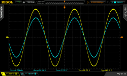
Nice! And all this with Triode Wired, and no negative feedback. Thanks for the schematic and the scope shot.
Nice! And all this with Triode Wired, and no negative feedback. Thanks for the schematic and the scope shot.
You are welcome. The goal was no negative feedback. The Anthem amp I am using has 2V outputs so it drives the circuit with no problem. Don't know if C1 3p cap is needed or not on the 12ax7 anode I never tried without it, for sure you need the 1K grid stoppers on the KT120's
You are absolutely correct! I must have had mind glitch 😱 If the both the plate and the cathode resistors are exactly the same then both the voltage gains are the same. Must be the age.....😀JoeAlders,
Huh?
Unless there is significant capacitive currents from the grid to the cathode and grid to the plate, and significant capacitive current from the cathode to the filament, or you have a gassy tube, then . . . <snip>
I once used a balance pot on a cathodyne... I found it to be useless. It was always set at one end... The end that was a short. YMMV but for me it was a waste of time and money. Now I have two decorative pots in an amp, and they are only still there because they fit the holes in the chassis 😛
Thanks All for the replies and sharing of your schematics and links - I learn something with every question asked here! Such as somehow perfectly balancing the outputs of this type of circuit is not particularly worthwhile - and it works as I suspected regarding voltage swing.
I had read on some other site selling auto bias boards that the signal levels to the output transformer - as well as the tube DC bias levels - need to be exactly the same.
I liked the link to John Broskie's Tubecad site, which kindled the idea of remote sensing for the amplifier' feedback. Nice! Ask a question about a cathodyne circuit, get led to another idea that may offer some benefit I can actually hear.
I once used a balance pot on a cathodyne... I found it to be useless. It was always set at one end... The end that was a short. YMMV but for me it was a waste of time and money. Now I have two decorative pots in an amp, and they are only still there because they fit the holes in the chassis 😛
Best regards!
Attachments

When someone is selling a solution to a problem, they have to convince you that you have the problem.jjasniew said:I had read on some other site selling auto bias boards that the signal levels to the output transformer - as well as the tube DC bias levels - need to be exactly the same.
The DC bias levels should be as close as possible to avoid core saturation. The signal "should be" the same amplitude, but not strictly required.
I use autobias boards all the time. I like the "set it and forget it" aspect, and the not having to rebias when I swap a tube.
I use autobias boards all the time. I like the "set it and forget it" aspect, and the not having to rebias when I swap a tube.
MelB,Scope trace is: blue trace = output attached to 6.8 ohm 50 watt resister and yellow trace = output of 12ax7. Looks pretty even at 45 watts out.
Which Rigol oscilloscope are you using?
Best regards!
Response #17, that picture:
LOL !
- Status
- Not open for further replies.
- Home
- Amplifiers
- Tubes / Valves
- How to balance a Cathodyne phase splitter?