Hi,
Did not find this topic in the forum using search so setup a new topic on this issue.
I have a subwoofer amp for the US with a 120vac requirement and unfortunately, unlike I have done before, it does not have a transformer which can be swapped out as it uses an switching PSU.
I'm looking for a non transformer alternative do step down from 240vac to 110vac rated at 500w @ 240vac.
Any ideas?
Help is appreciated.
Sinusoidal output or other? Since the 110V side is supposed to run an SMPS, non-sinusoidal should work just fine, don't you think?
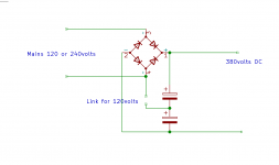
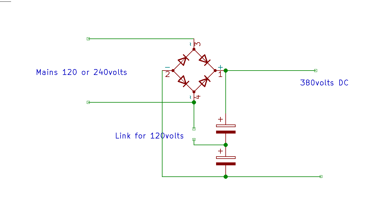
Easiest method: A 230V phase-controlled rectifier with 160V DC output directly feeding the 110V SMPS.
Easiest method: A 230V phase-controlled rectifier with 160V DC output directly feeding the 110V SMPS.
Last edited:
Not for modern PFC supplies. Either the PFC can handle the 100-240V range, or you are stuck at whatever voltage it was designed for.
I think I have designed a simple AC divider a number of years ago. I need to browse through my archives
I think I have designed a simple AC divider a number of years ago. I need to browse through my archives
As usual a picture would tell us more than 1000 words. The ones that can be changed with a jumper (like Icepower modules) have the jumper clearly marked. The ones that accept 100 - 240V have that often printed on the PCB despite the markings on the casing of the device that it is meant for 120V.
Last edited:
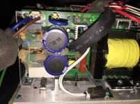
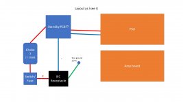
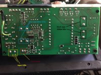
Attached are pictures of the PSU and a layout diagram as I see it.
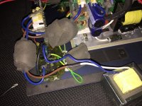
pic 2 - connections
pic 3 - choke?
pic 4 - Standby module?
pic 5 - PSU
pic 6 - bottom of PSU relative to Pic 5
pic 7 - mid area of PSU
pic 8 - mid right
pic 9 - mid left
pic 10 - top of PSU
Let me know if any more details are required.
Thanks
pic 2 - connections
pic 3 - choke?
pic 4 - Standby module?
pic 5 - PSU
pic 6 - bottom of PSU relative to Pic 5
pic 7 - mid area of PSU
pic 8 - mid right
pic 9 - mid left
pic 10 - top of PSU
Let me know if any more details are required.
Thanks
Attachments
-
 PSU 6.JPG648.6 KB · Views: 97
 -
 PSU 5.JPG734.7 KB · Views: 102
 -
 PSU 4.JPG717.6 KB · Views: 93
 -
 PSU 3.JPG685.9 KB · Views: 100
 -
 PSU 2a.JPG953.9 KB · Views: 242
 -
 PSU 1.JPG909.2 KB · Views: 120
 -
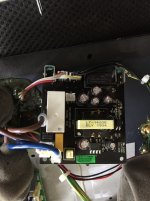 Standby Module.JPG822.7 KB · Views: 189
 -
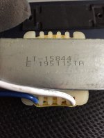 Choke.JPG336.9 KB · Views: 191
 -
 Layout.JPG498.1 KB · Views: 207
 -
 PSU Layout.jpg52.4 KB · Views: 212
Last edited:
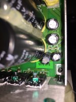
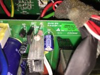
A. It has 2 caps what somewhat points to the jumper system. In cheap stuff "they" try to use a little parts as possible unless it is absolutely necessary.
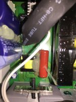
B. The jumper wire (blue) seems to be fitted and with a connector in this case. It is between the mains connector and Q3.
C. If the 2 x 680 µF 200V caps are in series when the jumper is removed they become a 400V DC capacitor which seems logical for 230V AC mains voltage.
However the manufacturer chose not to indicate this with text so this is still an assumption with high probability. For 100% certainty* you'll have to follow PCB tracks and make a simple drawing and compare to the drawing in post #3. You could also measure with the jumper mounted and without the jumper to check if there is continuity with either the L or N pins on the PCB. If things are as expected removing the jumper will make it a 230..240V PSU. Most elegant, stuff used as designed and no extra complexity required.
*Now despite not being the "just doing something" type in this case I would take a look to convince myself that it is like usual (logic: why would there be a jumper near the filter caps?) and then put it back together again and plug it in. When I was wrong I'd have a laugh and think to do it wiser next time. The gains would be that I'd have something to tell on an audio forum 😀
Last edited:
Please do us a favor. Report your own first post and have the thread title changed to "How to adapt a [insert device type here] to 240V mains?" or the like. It will make it easier for the people that help you AND it will make it easier for others that try to find out the same (hint: you won't find it either when not using the type number) AND it will cause your issue being solved faster. Win-win-win. It avoids the "Car for sale. Color:red" type of item.
BTW it is not 240vac but 240 V AC (or 240V AC). Using correct technical language is simply courtesy to technical readers and techs that use their time to help you.
BTW it is not 240vac but 240 V AC (or 240V AC). Using correct technical language is simply courtesy to technical readers and techs that use their time to help you.
Last edited:
 Title changed as OP requested
 Yes that will help owners of a Pioneer XL-A1 adapting theirs to 240V mains voltage tremendously 😀
*in the world of solving technical stuff one works with brand names and type numbers, sometimes also year of production. Those that search to solve their very important issue search for that type number if they're clever. Mentioning no type number makes it generic. Generic answers are rarely hit and most often miss. Hit and miss causes all involved loosing valuable time. Thank you.
*in the world of solving technical stuff one works with brand names and type numbers, sometimes also year of production. Those that search to solve their very important issue search for that type number if they're clever. Mentioning no type number makes it generic. Generic answers are rarely hit and most often miss. Hit and miss causes all involved loosing valuable time. Thank you.
Last edited:
1) JonSnell is right, as usual.
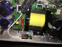
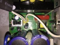
I see your pictures BUT seeing components from the top is incomplete data, since no labels are visible, so YOU label them for us.
I can *guess* but that´s not safe, specially here.

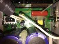
I GUESS those "818" blue caps are the high voltage ones but please confirm rating.
EDIT: maybe the actual bridge rectifier is the barely visible rectangle bottom left, submerged in a sea of silicone sealer.
Not too likely but hey! , I don´tbhave bthat PCB before me.
EDIT 2: in case it´s not clear: there is a high possibility that removing that blue wire you switch mains voltage, if so I´ll suggest the safe way to test it.
I GUESS that "M" black rectangle s the high voltage/mains bridge but please confirm rating/labels ; in both cases even better if you post sideways pics showing labelling.
IF they are what I´m guessing, then Jon Snell´s circuit example applies:
and then determining what do you have there becomes simpler.
Theory:
* Main switcher works from rectified 380V DC taken from top cap positive to bottom cap negative, always.
* With 240VAC mains, bridge works like a normal bridge rectifier (so NO link) , you straight get 380VDC end to end.
* with 120VAC mains, you add the LINK, which shorts one mains wire and also one "~" (AC) labelled diode leg to series caps center connection (from lower positive to upper negative), 2 bottom diodes at the bridge become reverse biased and so "disconnected" for all practical means, and 2 top ones now become a voltage doubler, top right charges top cap to +190VDC , top left charges bottom cap to -190VDC, beauty is you STILL have 380VDC end to end, main switcher is happy.
back to practice: I GUESS the blue wire is the LINK, as mentioned by jean paul, but we need confirmation.
Plan A: draw the schematic since you have the actual PCB
Plan B: (simpler): just identify the "~" labelled pins at the mains bridge (IF "M" is the mains bridge) and fllow tracks: one track must go towards the caps center point , and passing through the blue jumper: YES/NO , confirm one.
So homework is:
* identify/label/show supposed bridge and caps labels
* follow tracks leaving bridge "~" and find if one goes to caps center point through the supposed jumper.
* post results.
I see your pictures BUT seeing components from the top is incomplete data, since no labels are visible, so YOU label them for us.
I can *guess* but that´s not safe, specially here.
I GUESS those "818" blue caps are the high voltage ones but please confirm rating.
EDIT: maybe the actual bridge rectifier is the barely visible rectangle bottom left, submerged in a sea of silicone sealer.
Not too likely but hey! , I don´tbhave bthat PCB before me.
EDIT 2: in case it´s not clear: there is a high possibility that removing that blue wire you switch mains voltage, if so I´ll suggest the safe way to test it.
I GUESS that "M" black rectangle s the high voltage/mains bridge but please confirm rating/labels ; in both cases even better if you post sideways pics showing labelling.
IF they are what I´m guessing, then Jon Snell´s circuit example applies:
and then determining what do you have there becomes simpler.
Theory:
* Main switcher works from rectified 380V DC taken from top cap positive to bottom cap negative, always.
* With 240VAC mains, bridge works like a normal bridge rectifier (so NO link) , you straight get 380VDC end to end.
* with 120VAC mains, you add the LINK, which shorts one mains wire and also one "~" (AC) labelled diode leg to series caps center connection (from lower positive to upper negative), 2 bottom diodes at the bridge become reverse biased and so "disconnected" for all practical means, and 2 top ones now become a voltage doubler, top right charges top cap to +190VDC , top left charges bottom cap to -190VDC, beauty is you STILL have 380VDC end to end, main switcher is happy.
back to practice: I GUESS the blue wire is the LINK, as mentioned by jean paul, but we need confirmation.
Plan A: draw the schematic since you have the actual PCB
Plan B: (simpler): just identify the "~" labelled pins at the mains bridge (IF "M" is the mains bridge) and fllow tracks: one track must go towards the caps center point , and passing through the blue jumper: YES/NO , confirm one.
So homework is:
* identify/label/show supposed bridge and caps labels
* follow tracks leaving bridge "~" and find if one goes to caps center point through the supposed jumper.
* post results.
Last edited:
Now that adds a lot 🙂
But true, better safe than sorry. In this specific case one could rely on a safe distance and the fuses.
AvMania, please let us know if the advice was OK. Feedback works.
But true, better safe than sorry. In this specific case one could rely on a safe distance and the fuses.
AvMania, please let us know if the advice was OK. Feedback works.
Last edited:
Blue caps 0818 are 680uf 200v black caps 3300uf 80v pic attached.
also some I had not included before.
also some I had not included before.
Attachments


Ok, one task completed, mor still pending.
Dark green over dark green has zero contrast, it´s very hard to follow tracks from your pictures, you will have to check thatb for use.
We still need you showing us the "M" rectangle on that picture, as well as thenother mystery rectangle and confirm tracks continuity with a meter setb to low ohms, "beep" continuitybtest is not enough because it has no units.
Short meter probes together and tell us what is the residual/remaining ohm number shown (it will not be zero)
Use lowest ohm scale, usually 200 ohm.
To me it was already clear but what about the brand and typenumber and then search the service manual/schematic? If one wants to be 100% sure that would be a good way.
This is post #18 and we are still level “Car for sale. Color: red” 🙂
This is post #18 and we are still level “Car for sale. Color: red” 🙂
At least now we have door and engine cover closeups. taken from 10cm away, and we can confirm the car is GREEN, dark green in fact.

And you think we are not going forward? 😛
Seriously, not sure why/how
Oh well.
And you think we are not going forward? 😛
Seriously, not sure why/how
and it´s STILL obscure:Title changed as OP requested
How to adapt a 120V amp to 240V mains
Oh well.
Last edited:
Please do us a favor. Report your own first post and have the thread title changed to "How to adapt a [insert device type here] to 240V mains?" or the like. It will make it easier for the people that help you AND it will make it easier for others that try to find out the same (hint: you won't find it either when not using the type number) AND it will cause your issue being solved faster. Win-win-win. It avoids the "Car for sale. Color:red" type of item.
BTW it is not 240vac but 240 V AC (or 240V AC). Using correct technical language is simply courtesy to technical readers and techs that use their time to help you.
Was done as requested. If you have a better title you should have said so. I will not put the device name as yet until I finish talking to the manufacturer to try and get their help.
- Home
- Amplifiers
- Power Supplies
- How to adapt a REL S510 from 120V to 240V mains